Arduino DTMF Controlled Robot MKR GSM 1400 Tutorial
Arduino MKR GSM 1400 is the latest of Arduino’s MKR series which combines MKR Zero and an inbuilt GSM module that support 3G and cellular Connectivity. In this tutorial, I will show you how you can make a robot that can be controlled using DTMF tones.

Sponsor Link
This Project is Sponsored by UTSource. UTSource is a professional electronic components supplier.
What is DTMF?
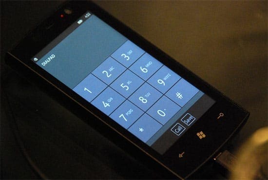
DTMF or Dual Tone Multi Frequency or Touch Tone is tone that is a combination of two specific frequencies that is produced when a button is pressed on the phone.
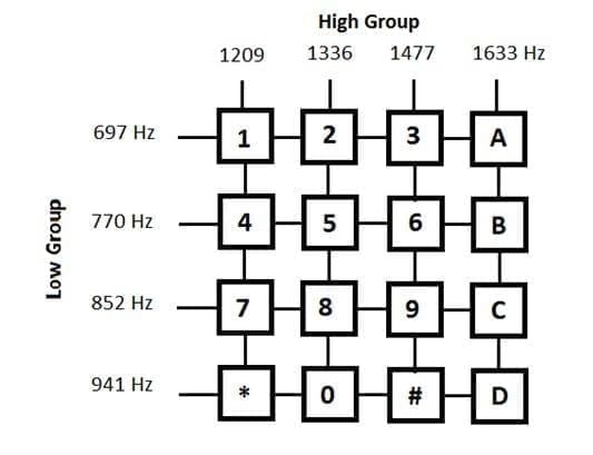
These two frequencies are selected in such a way that, one of them is from a high frequency group and the other is a low frequency group. This is done in order to avoid interference from external sound sources. This method can be used for dialing a number, transfer a message from the phone to the station or one phone to another phone. In our case, we will be making use of this DTMF tones to control our robot.
Components Required
Click on them to purchase from amazon
- Arduino MKR GSM 1400
- A 12V Battery
- DC motors
- Chasis
- L293D Motor Driver IC
Instructions
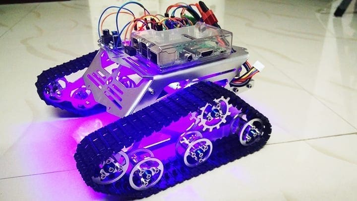
Step 1 – Building The Chasis
First let us set up the chasis. You can build it the way you like. It should have enough space to stick your Arduino MKR GSM 1400, L293D Motor Driver Board and the LIPO battery. You can use foam board or aluminum to build the base. If you want you can purchase one from here.
Step 2 – Power Source
In this project, I will be using a 12V Lithium Polymer battery to power up the whole robot, that is the Raspberry Pi and L293D Motor Driver to drive the motors. We can provide 12 V directly to the motor driver Board as it have an inbuilt regulator to power the motor and Circuit separately. But powering raspberry pi with this 12 V battery will fry the Chips. So you will have to use a regulator to step down the 12V to 5V and supply it to Pi. You can Purchase your Lithium Polymer Battery From Here.
Step 3 – The DC Motor
Here, I will use 2 100 RPM DC motors. These DC motors are driven using a Dual H Bridge Motor Driver IC – L293D. More details on driving DC motors using L293D IC can be obtained here. If you are new to this, I recommend you to go through the article first for better understanding.
Get your Products – L293D Driver Board
Learn More About L293D Motor Driver IC
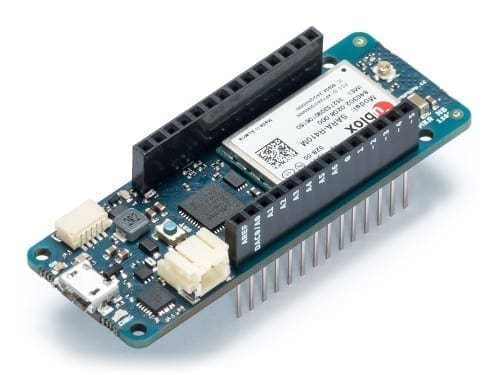
Step 4 – Arduino GSM 1400
Arduino GSM 1400 is the latest board in the Arduino series that combines the MKR 1000 with global GSM connectivity.[AdSense-C]The board is powered by SAMD21 Cortext MO, 32 bit ARM MCU with a flash memory of 256 KB and an SRAM of 32 KB. It have a total of 8 Digital IO Pins (0-7), 7 Analog Input Pins (A0 – A6), 1 Analog Output Pin and 12 PWM Pins with support for UART, SPI and I2C Communication protocols.

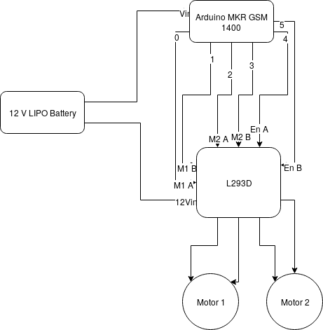
Step 5 – Connections
Arduino should be provided with 5V or 12 V through Vin and L293D Motor Driver with 12 V.
For this project we will be using 6 GPIO pins to control the robot. 0 and 1 for Motor 1, 2 and 3 for Motor 2 and 4 and 5 for Enable Pins. 4 and 5 should be always kept at Logic 1.
Inorder to upload the code to arduino, you have to add Arduino MKR GSM 1400 to the boards manager. Follow this instructions to install and set up arduino IDE for this project.
The Code
Just copy this code, paste it in Arduino IDE and upload it to your board.[AdSense-A]
/*
Code to Control a Robot Using DTMF signals using Arduino MKR GSM 1400
Logon to www.rootsaid.com for complete tutorial
*/

#include <MKRGSM.h>

GSMVoiceCall rts;
GSM gsmAccess;


char number[15]; //Store Mobile Number

void setup() {
 Serial.begin(9600);
 boolean notConnected = true;
 Serial.print("Initiating..");

 while (notConnected) {
 if (gsmAccess.begin() == GSM_READY) {
 notConnected = false;
 Serial.println("Link Ready");
 } else {
 Serial.println("Not Connected");
 delay(1000);
 }
 }
 rts.hangCall();
}

void loop() {

switch (rts.getvoiceCallStatus()) {

case RECEIVINGCALL:
 Serial.println("Receiving call from ");
 rts.retrieveCallingNumber(number, 15);
 Serial.print("Number:");
 Serial.println(number);
 rts.answerCall();
 break;

case TALKING:
 Serial.println("Call Answered.. Waiting for Input");

int dtmf = -1;
 do {
 if (rts.getvoiceCallStatus() != TALKING) {
 rts.hangCall();
 Serial.println("Terminating Call");
 }
 else {
 dtmf = rts.readDTMF();
 switch (dtmf) {
 case '2': forward(); break;
 case '4': left(); break;
 case '5': stop(); break;
 case '6': right(); break;
 case '8': backward(); break;
 }
 }
 }
 while ((dtmf < 0) && (rts.getvoiceCallStatus() == TALKING));
 Serial.println("Pressed button: ");
 Serial.println(dtmf);
 break;
 }
}

void stop()
{
digitalWrite(0, LOW);
digitalWrite(1, LOW);
digitalWrite(2, LOW);
digitalWrite(3, LOW);
digitalWrite(4, LOW);
digitalWrite(5, LOW);
}
void forward()
{
digitalWrite(0, HIGH);
digitalWrite(1, LOW);
digitalWrite(2, HIGH);
digitalWrite(3, LOW);
digitalWrite(4, HIGH);
digitalWrite(5, HIGH);
}
void backward()
{
digitalWrite(0, LOW);
digitalWrite(1, HIGH);
digitalWrite(2, LOW);
digitalWrite(3, HIGH);
digitalWrite(4, HIGH);
digitalWrite(5, HIGH);
}
void left()
{
digitalWrite(0, HIGH);
digitalWrite(1, LOW);
digitalWrite(2, LOW);
digitalWrite(3, LOW);
digitalWrite(4, HIGH);
digitalWrite(5, HIGH);
}
void right()
{
digitalWrite(0, LOW);
digitalWrite(1, LOW);
digitalWrite(2, HIGH);
digitalWrite(3, LOW);
digitalWrite(4, HIGH);
digitalWrite(5, HIGH);
}
Drive
Insert a valid SIM card to the arduino and power on the bot. Now call to that mobile number from another phone. If everything you have done is correct, the call will be automatically answered and will wait for you to dial numbers. The key mapping is shown below.[AdSense-C]
2 – UP
8 – DOWN
4 – LEFT
6 – RIGHT
5 – STOP
You can easily drive the bot by pressing these buttons.
If you have any questions or if you are stuck somewhere, feel free to ask it in the comments. You can also discuss the topic in RootSaid whatsapp group. Click on this link to join the group.