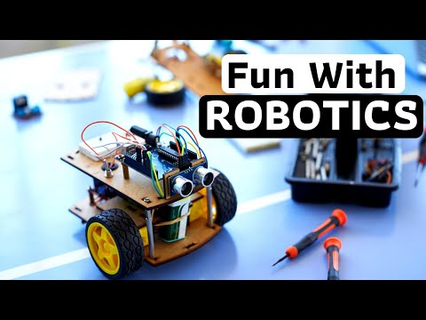
Well, guys this is one of the project that never gets old. This was the first thing I did when I started learning about Arduino. An Arduino Line Follower Robot – A Line Follower Robot Using Arduino UNO and IR Sensor, which follows a line without user interaction. A small autonomous robot which will “see” and follow the line and take decision when it sees a turn by itself.
Why not make a PCB for your Project?
Making a PCB for your DIY project is not hard nowadays. PCB helps to get rid of all messy wires and stuff and gives your project an awesome look. And it’s cool to make your own PCB for your project right?
I use Altium Designer to draw the circuit and design the PCB. It is a powerful tool that can be used to design and create your own PCBs for your project as well as complex and multiplayer PCBs for industrial use. Here is the link to the Altium trial version. So make sure you check it out.
I use Altium Designer to draw the circuit and design the PCB. It is a powerful tool that can be used to design and create your own PCBs for your project as well as complex and multiplayer PCBs for industrial use. Here is the link to the Altium trial version. So make sure you check it out.
We have a beginners guide on “Getting Started with Robotics” which will give you a kick start in this field. Check out our free video tutorial below for a brief introduction.
Robotics for Kids and Beginners
Line Follower Robot Using Arduino UNO and IR Sensor
In this tutorial, we will discuss the working of an Arduino line following robot which will follow a black line in white background and take the correct turn whenever it reaches curves in its path.
Before jumping into line following robot tutorial, let’s get familiarized with the components used. If you are an expert and familiar with these components you can skip this section and straight away jump to the tutorial and start building Arduino Line Follower.
The Chasis of the Arduino Line Follower Robot
The first thing to do is build a chassis for WiFi Robot using Arduino. You can build it the way you like. The only thing you should keep in mind is, it should have enough space for Arduino, L293D Motor Driver, and a LIPO battery. For our project, I will be using a 12V LiPo Battery. You can use foam board or aluminum sheet or wood piece for building the base.
These are some of the best robot chassis available for you to build this project. Check out the link below.
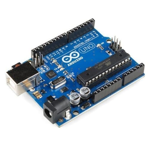
You all might be familiar with Arduino; which is the most widely used and fastly evolving electronic platform with so many microcontroller boards and software. For our line following robot, I will be using Arduino UNO which is the most commonly used board. The Arduino UNO is the best option to get started with electronics and coding if this is your first experience with Arduino Platform. You can use any Arduino Board for this project.
IR Sensor
As mentioned earlier, our line following robot will be following a black line in a white background. So we need something that will ‘see’ the line and tell the line follower to follow the line or to turn around if it is going away from the line. For this purpose, we will be using an IR (Infra Red) Sensor.
This IR sensor mainly consists of an IR transmitter (IR LED) and an IR receiver. IR LED always emits IR rays to the direction it is pointing to. When the IR rays hit a surface, some rays will be reflected back depending upon the color of the surface. Means, the brighter the color is, the more IR will be reflected back. Darker the color is, more IR will be absorbed by the surface and lesser IR rays will be reflected back.
These reflected rays are sensed by the IR receiver and depending upon the received IR rays, the resistance of the receiver varies which will, in turn, varies the output voltage.
Thus it is possible to sense the color of the surface where the robot is running by looking into the reflected IR rays. So it is very easy to measure how bright the surface is which will make it easy for us to track the line.
There are so many cheap IR sensors available online; you can purchase any of them. You will need at least two of them for making the line follower robot.
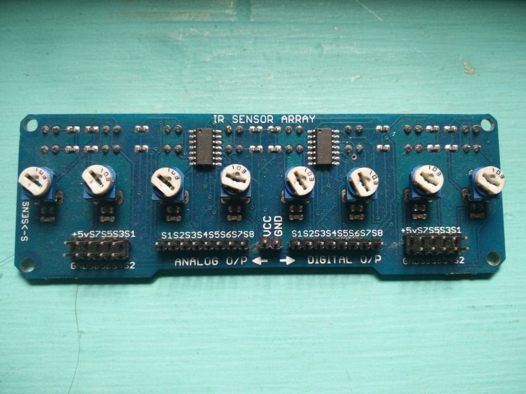
IR Sensor Array (Optional)
For an ordinary Line follower robot, two IR sensors are enough. But if you are planning to take that to the next level with some advanced movements or PID Algorithm integration (which I will be covering in the next chapter), it would be better if your line follower gets some extra eyes. You could either add the number of individual IR Sensors, which is quite messy and power consuming, or you could buy or build an array of sensors in a single board. This can be called as an IR Sensor Array.
An IR Array board consist of 4-9 pairs of IR Transmitters and Receivers arranged in a line. Most of the array boards will be having a potentiometer for each sensor to control the sensitivity of the sensor. Also in most cases, you will be having provision to extract digital value as well as analog values from the sensors. These analog values can be used to calculate error levels while using the PID Algorithm.
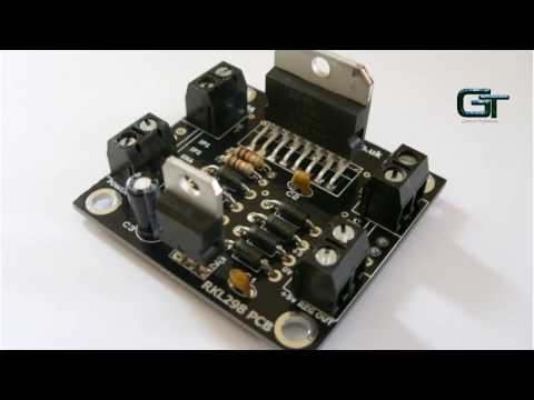
H Bridge and L293D Motor Driver
An H-bridge can be any switching circuit using Bipolar Junction Transistors (BJT) or Field Effect Transistors ( MOSFET or MESFET) which allows a voltage to be applied across a DC motor without making physical or hardware changes in the circuit. H Bridge circuits are widely used in the field of robotics to switch the direction of DC motor rotation as well as for creating square waves for so many purposes.
L293D is a 16 pin compact H Bridge circuit available in the form of an IC. The advantage of using L293D is, since there are two H Bridge circuits in one IC, you can control two DC motors simultaneously using a single chip. In this project, we will be using this IC to drive the motors in our line following robot.
Lets Get Started with Line Follower Robot Using Arduino UNO and IR Sensor
Let us Build a Line Follower Robot Using Arduino UNO and IR Sensor – A Simple Arduino Line Follower Robot.
Step 1 – Setting up the IR Sensors
Let us start building our line following robot arduino by testing out the IR Sensors and getting the readings out of them. You can either use individual sensors or the array sensor for our Line Following Robot (I recommend IR sensor array). I will explain both.
Method 1 – Using individual sensors
Most of the individual sensors will be somewhat like this.
It will be having 3 pins. One for VCC (5V), GND (0V) and Vout (Output Voltage). Connect them as follows.
Once the code is uploaded, open the serial monitor and you will see output like this
0 -- 0

0 -- 1

0 -- 1

1 -- 1

1 -- 1
These values will be changing depending upon the surface where you are pointing this sensors.
Note: If you are using sensors with analog output, and use analogRead instead of digitalRead you will be getting values from 0 to 1023.
Method 2 – IR sensor Array
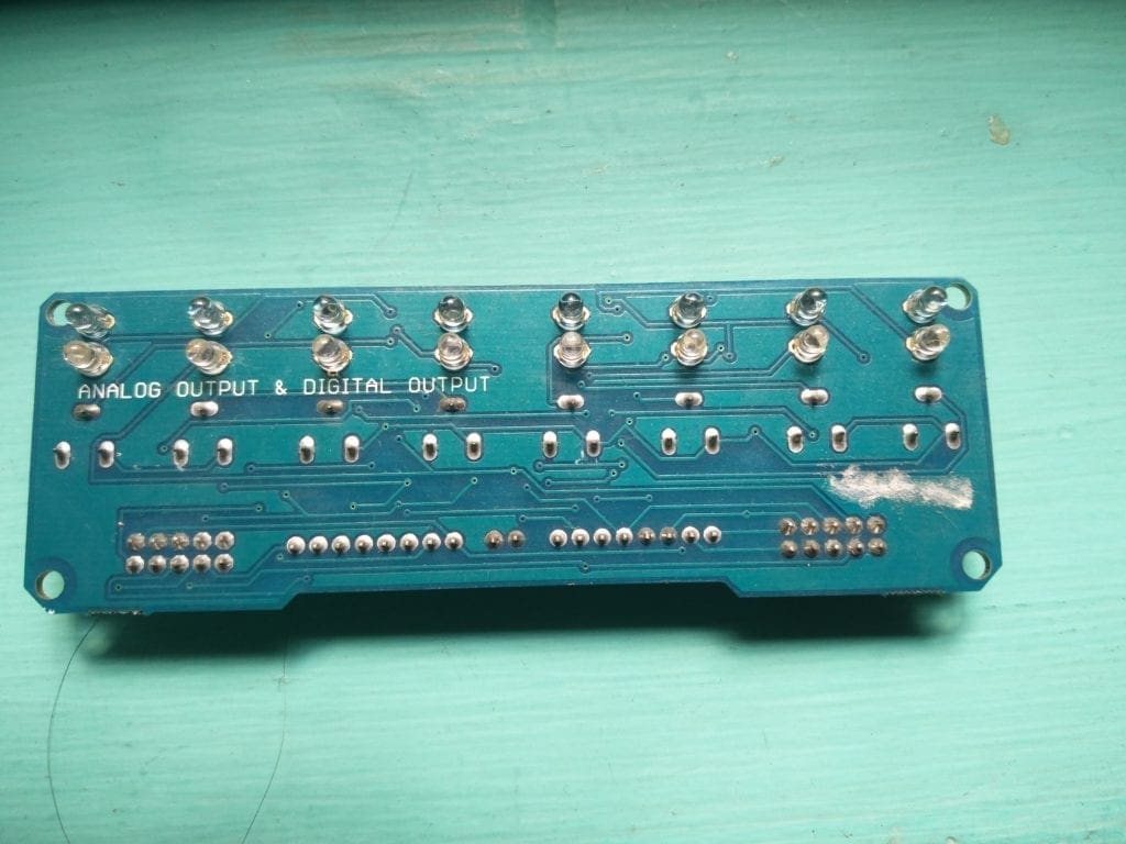
Shown below is a typical IR Array sensor having 8 pairs of IR Transmitter and Receiver – 8 Sensor units.
It will be having 2 pins – One for VCC (5V), GND (0V) and Vout (Output Voltage) from 8 sensors. Since we are using Arduino Nano, we can only using 6 of them. Connect them as follows.
IR Sensor —–> Arduino
5V —–> 5Vout of Arduino
GND —–> GND of Arduino
Vout of IR Sensor 1 —–> A0 of Arduino
Vout of IR Sensor 2 —–> A1 of Arduino
Vout of IR Sensor 3 —–> A2 of Arduino
Vout of IR Sensor 4 —–> A3 of Arduino
Vout of IR Sensor 5 —–> A4 of Arduino
Vout of IR Sensor 6 —–> A5 of Arduino
Upload the below code and see if it is working.
Code
void setup() {
Serial.begin(9600);
}
void loop()
{
int s1 = digitalRead(A0);
int s2 = digitalRead(A1);
int s3 = digitalRead(A2);
int s4 = digitalRead(A3);
int s5 = digitalRead(A4);
int s6 = digitalRead(A5);
Serial.print(s1);
Serial.print(" -- ");
Serial.print(s2);
Serial.print(" -- ");
Serial.print(s3);
Serial.print(" -- ");
Serial.print(s4);
Serial.print(" -- ");
Serial.print(s5);
Serial.print(" -- ");
Serial.print(s6);
Serial.println("");
Serial.println("");
delay(100);
}
Once the code is uploaded, open the serial monitor and you will see output like this
These values will be changing depending upon the surface where you are pointing these sensors.
Note: If you are using sensors with analog output, and use analogRead instead of digitalRead you will be getting values from 0 to 1023.
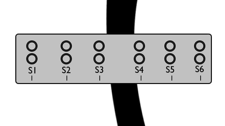
What do these outputs means?
Sensor output ‘1’ means that most of the IR rays are reflected back to the sensor and the surface which is pointed by the sensor is white. And sensor output ‘0’ means that most of the rays are absorbed and the surface is black.
When the arduino line follower is on track, the line will be in between the two sensors and will be pointing to the white surface. Which means the output of all the sensors will be 1. In that condition, the line following robot should move forward.
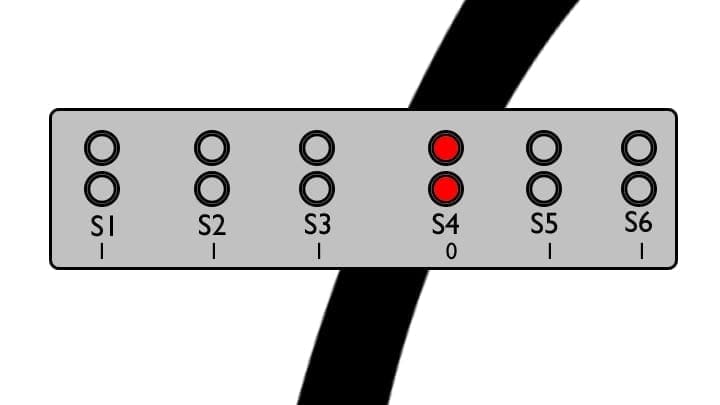
When there is a right turn on the track, the first sensor that crosses the line will be S4 and all other sensors will be pointing white surface. Thus the output of S4 will be 0 and all others will be 1. In this case out Arduino line follower should turn right.
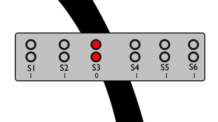
When there is a Left turn on the track, the first sensor that crosses the line will be S3 and all other sensors will be pointing white surface. Thus the output of S3 will be 0 and all others will be 1. In this case out Arduino line follower should turn left.
Awesome. Now you can move to the next step and start building our line following robot arduino.
Step 2 – Building the Robot
Now let us start building the Robot of our Arduino Line Follower. Here we are going to build a 4 wheeled robot, with 2 DC Motors connected on either side (front) and two dummy wheels on the back side. As mentioed earlier, we will be using Arduino UNO board to get input from the sensors, process them and send signals to L293D motor driver IC to drive the DC motor motor of Line Following Robot Arduino.
L293D for Line Follower Robot Using Arduino UNO and IR Sensor
Below you can pin out diagram of the L293D IC. As you can see it has two pins for inputting voltage. One of them is for powering the internal circuit of the IC and the other for driving the motor.
Pin 8 – Driving the Motors – 4.5 V to 33 V Pin 16 – Working of the IC– 5V
If you happen to reverse this connection accidentally, you may burn off the chip.
This IC have two H Bridge circuits and so it is capable of controlling two motors individually at the same time. One side of this IC controls one motor and the other side controls the second motor. For the motor to work, the Enable pin of that side should be High. The enable pins can also be used to control the speed of the motor using PWM (Pulse Width Modulation). If you want to know more about L293D and working of H-Bridge, follow the link below.
So we have two wheels. How does this line follower goes forward, backward, left or right?The logic is pretty simple.
When both motors rotate the same direction (clock wise or anti clock wise), the arduino line follower will move forward or backward. If both moves in opposite direction, the line following robot will turn left or right.
Motor 1 (Left Side) ——— Motor 2 (Right Side) —————-Robot Status
Clockwise—————————- Clockwise————————–Forward
Clockwise——————————— Stop —————————-Right
Clockwise————————- Anti Clockwise ——————– Sharp Right
Stop———————————— Clock wise ————————Left
Anti Clock wise——————— Clock wise ———————–Sharp Left
Anti Clockwise—————— Anti Clockwise ———————Backward
Simple as that. 🙂
Step 3 – The Connections
Now let us connect our L293D and sensors to Arduino Uno
L293D
5Vcc – 5V of Arduino
5-32 Vcc2 – 12 V LiPo Battery
Gnd – Gnd of Arduino
Motor 1
Enable – GPIO 6
In 10 – GPIO 10
In 11 – GPIO 11
Motor 2
Enable – GPIO 7
In 12 – GPIO 12
In 13 – GPIO 13
IR Sensor (Individual) – For Method 1
IR Sensor —–> Arduino
5V —–> 5Vout of Arduino
GND —–> GND of Arduino
Vout of IR Sensor 1 —–> A0 of Arduino
Vout of IR Sensor 2 —–> A1 of Arduino
Sensors (Sensor Array) – For Method 2
IR Sensor —–> Arduino
5V —–> 5Vout of Arduino
GND —–> GND of Arduino
Vout of IR Sensor 1 —–> A0 of Arduino
Vout of IR Sensor 2 —–> A1 of Arduino
Vout of IR Sensor 3 —–> A2 of Arduino
Vout of IR Sensor 4 —–> A3 of Arduino
Vout of IR Sensor 5 —–> A4 of Arduino
Vout of IR Sensor 6 —–> A5 of Arduino
Our Arduino Line Follower is now ready for action. Line follower code is available for download from our repository. Links are provided below
The code is really easy to understand and if you have any queries regarding the codes, feel free ask it in the comments or in our community.
Upload the code, power up, and place your Arduino Line Follower Robot in black line and see the robot in action.
Had fun? In the next chapter, I will show you how to include PID Algorithm in our Arduino Line Follower to make our robot more smooth and fast by controlling the speed of the motor. Subscribe RootSaid for more awesome projects.
Arduino pH Meter Introduction AAs you all know, pH is a very important unit for measurement of acidity/basic nature of solutions. pH measurement is widely employed in almost every aspects of our life of applications such as agriculture, industries, environmental pollution monitoring, wastewater treatment and in research and development. pH is a measure of the…
In this series, we will build Spinel Crux, a Gesture Controlled Robot which can travel through rough terrain and can be controlled using hand gestures. To control the robot, we will be using control glove, which will have an accelerometer and a flex sensor to control the status and the direction it should move. The…
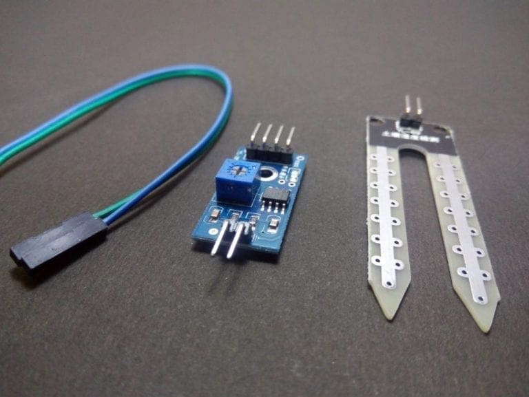
In this post, I will show you how you can use a moisture sensor with arduino to measure the moisture/water content of a place. This can be used to sense rainfall in smart weather sensors, water content of the soil for smart irrigation projects etc. Arduino can be easily programmed to work with this moisture…
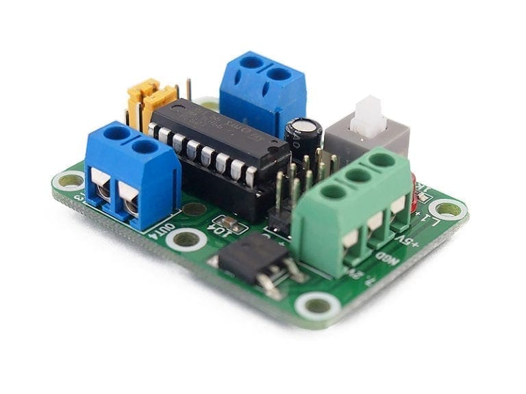
H bridge is simply a circuit that allows a voltage to be applied across a load in either direction. They are commonly used for controlling DC motor in moving parts of robots. The advantage of using DC motor is that, we can reverse the polarity of applied voltage across the load without modifying the circuit….
Hey guys, welcome back, In the previous post, I told you how an IR sensor works and how to make a line follower using an IR sensor. In this post, i will show you how you can make a Simple DIY Burglar Alarm using an IR sensor and a Buzzer without using any micro controller…
Arduino Coding Tips and Tricks for Beginners – Write reusable, easily readable and understandable code for your projects.
One Comment
Please can you send me the full programme code using 8 Array IR sensor because i dont know about it very much and can you send me code of the the line follow using 8 array but using of PWD for more accuracy in the robot.
My Email is already given below


Please can you send me the full programme code using 8 Array IR sensor because i dont know about it very much and can you send me code of the the line follow using 8 array but using of PWD for more accuracy in the robot.
My Email is already given below