Arduino Motor Shield PCB V1 | 4 Motors at Once
Hey guys, welcome back. In my previous post, I explained what an H Bridge Circuit is, L293D motor driver IC and piggybacking L293D Motor driver IC for driving high current motor drivers. In this post, I will show you how you can design and make your own L293D motor Driver Board, that can control upto 4 high current DC motors independently and get your own Arduino Motor Shield PCB done using JLCPCB.[AdSense-C]
Introduction to Arduino Motor Shield
H Bridge
H Bridge is simply a circuit that allows a voltage to be applied across a load in either direction. They are commonly used for controlling DC motor in moving parts of robots. The advantage of using DC motor is thathttp://rootsaid.com//arduino-gesture-controller/, we can reverse the polarity of applied voltage across the load without modifying the circuit.
If you want to know more about this H Bridge circuit, check out this link.
L293D
L293D is a compact form of H Bridge circuit in the form of an IC that employs the above mentioned circuit. It is an IC with 8 pins on each side (16 pins in total) which contains 2 independent H Bridge circuits, which means, we can control two motors independently using a Single IC.
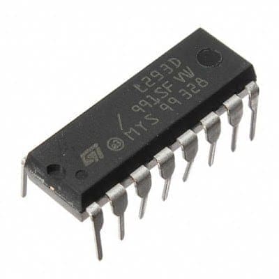
L293D is a typical Motor driver or Motor Driver IC which allows DC motor to drive on either direction. L293D is a 16-pin IC which can control a set of two DC motors simultaneously in any direction. It means that you can control two DC motor with a single L293D IC.
Learn more about L293D IC
Piggybacking L293D
L293D piggyback configuration is an Easy Way to Double (or in my case triple) The Current as well as the power of L293D Motor Driver IC to drive high torque/ high current motor/ high resistance load. (This strategy should work for any L293D chips). L293D Piggyback is a speedy and simple technique to double the current output to the motor.
So the entire thought is to solder another L293D chip straightforwardly over the present one. Pin to Pin. This puts the two chips in parallel mode so the voltage will remain the same as before but the current increases. These chips are evaluated at about 600ma constant or up to 1.2A for a brief period. After piggybacking two of them together, they will provide output with 1.2A persistent current and 2.4A for brief periods.
Arduino Pro Mini
This teeny tiny board was developed for applications and projects where space is premium and installations are made permanent.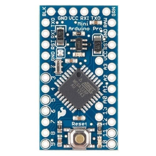
Small, available in 3.3 V and 5 V versions, powered by ATmega328. Due to its small size, in this project we will be using this board to control Arduino Based Motor Driver Board.
Online PCB Manufacturer – JLCPCB
JLCPCB is one of the best Online PCB manufacturing company from where you can order PCBs online without any hassle. The company works 24 hours a day, 7 days a week nonstop. With their high tech machinery and automated work stream, they can manufacture huge quantities of high-class PCBs within hours.

JLCPCB can develop PCBs of various complexity. They develop Simple and cheap PCBs with Single layer board for hobbyists and enthusiasts as well as complex multi layer board for high standard industrial applications. JLC works with large product manufacturers and may be the PCB of devices you are using such as laptop or mobile phones were made at this factory.
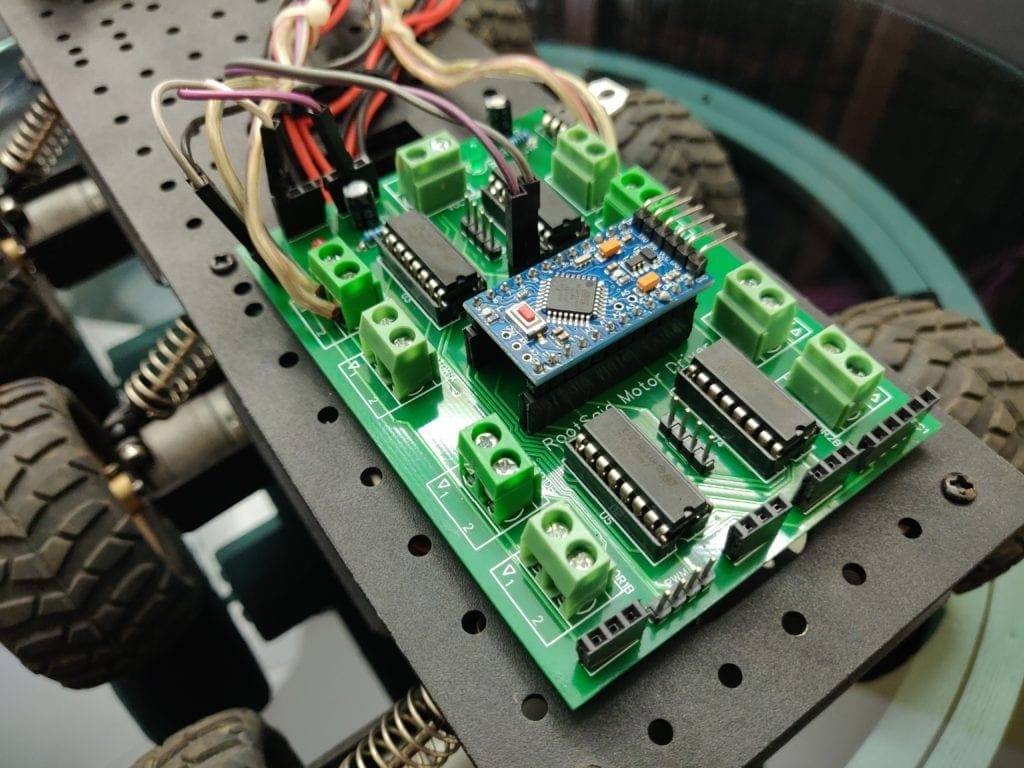
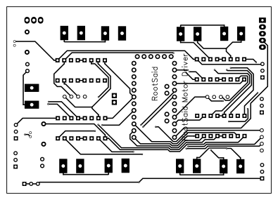
Arduino Motor Shield Board Explained
Features of RootSaid Arduino Motor Shield
- Controls 4 Motors Independently at a time
- Independent Speed Control
- Headers for Connecting Analog/Digital Sensors
- 5 V, 12 V and Gnd Headers for extra components
- Piggybacking without soldering
- Support HC12 Wireless Module
Now let us take a look at the circuit of our motor driver board.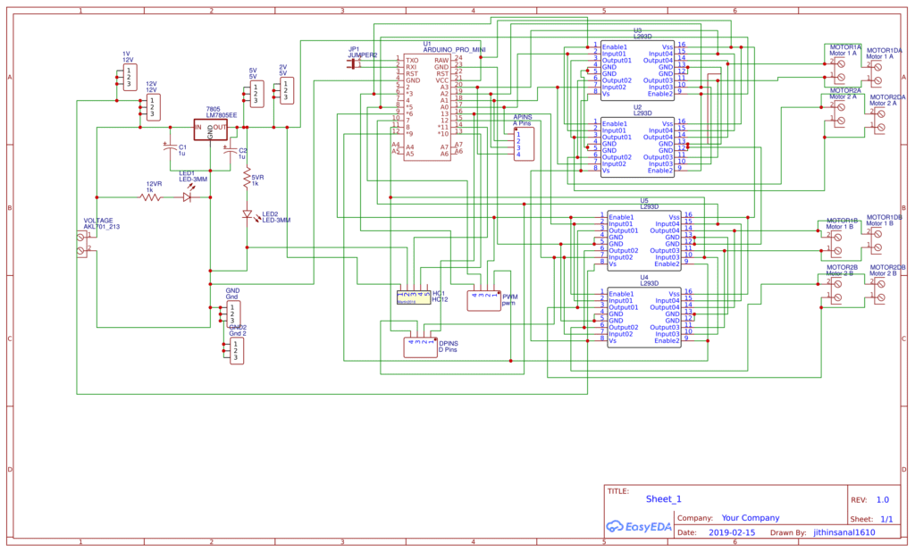
Looks a bit messy? Don’t worry, I will explain it for you.
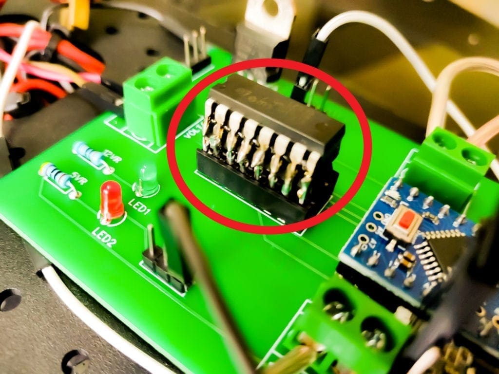
The Regulator
The input power is connected to a 7805 regulator. 7805 is a 5V regulator which will convert an input voltage of 7- 32V to a steady 5V DC supply. 5 V supply is connected to voltage input of Arduino as well as for Logical operations of L293D IC. There are indicator LEDs across 12V and 5V terminals for easy troubleshooting.
So, you can connect an input voltage of anywhere between 7V to 32 to this circuit. For my bot, I prefer a 11.1V Lipo Battery.
Piggybacked L293D Configuration
There is space for 4 L293D ICs on the PCB. U2 and U3 are parallely connected and U4 and U5 are parallely connected. This will help you to drive 4 high current DC motors independently at the same time with out much of an issue.
Make Your Own Arduino Motor Shield PCB
Now let me tell You How I designed the circuit and got this PCB done from JLCPCB.
[AdSense-C]
Step 1 – Creating the prototype
First connect all the components together on the breadboard so that I can troubleshoot easily if something goes wrong. Once I got everything working properly, I tried it on a Robot and played with it for some time. That time, I made sure that the Circuit is working properly and is not heating up.
Step 2 – The Schematics
To draw circuits and design PCBs, we have online PCB designing tools from EasyEDA, provides all the necessary capability for online PCB Design and PCB Printing of Circuit Boards with hundreds of components and multiple layers with thousands of tracks.
I drew a circuit in EasyEDA which included all the components on the breadboard – the ICs, Arduino Nano and HC12 module which are connected to the digital pin of the Arduino. I have also added some headers which are connected to Analog Pins and Digital Pins of These buttons will be useful in the future.
Connections
Also, there are 5V, 12V, Gnd, wireless module, digital and analog pin headers incase you want to add sensors and take readings in the future. Complete pin mapping is explained in below sections.
Motor Driver 1
Enable 1 – D3 (PWM)
InM1A – A0
InM1B – A1
Enable 2 – D5 (PWM)
InM2A – A2
InM2B – A3
Motor Driver 2
Enable 1 – 6 (PWM)
InM1A – D13
InM1B – D12
Enable 2 – 9 (PWM)
InM2A – D8
InM2B – D7
HC12
Vin – 5V
Gnd – Gnd
Tx/Rx – D10
Tx/Rx – D11
I also added a 7805, regulator which will helped me to provide an input voltage between 7 volt and 35 volt in the input, so that I can use a 7 volt power supply, 9-volt battery or even a 12 volt lithium polymer battery without any issues.
Step 3 – Creating PCB Layout
Next, designing the PCB. PCB Layout is actually a significant part of PCB Design, we use PCB Layouts to make PCBs from schematics. I designed a PCB where I could solder all the components together.
For that, first save the schematics and from the top tool list, Click on the convert button and Select “Convert to PCB”.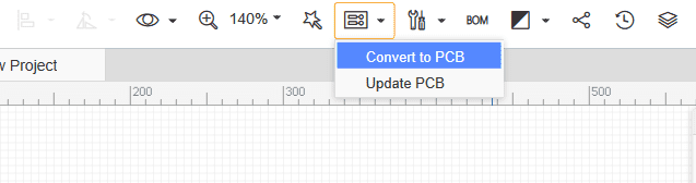
This will open up a window. Here, you can place the components inside the boundary and arrange them the way you want. The easy way route all the component is “auto-route” process. For that, Click on the “Route” Tool and Select “Auto Router”.
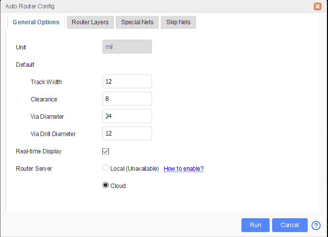
This will open up an Auto Router Config Page where you can provide details such as clearance, track width, layer information etc. Once you have done that, click on “Run”.
Here is the link to EasyEDA Schematics and Gerber Files of L293D Arduino Motor Shield Board . Please feel free to download or edit the schematics/PCB layout.
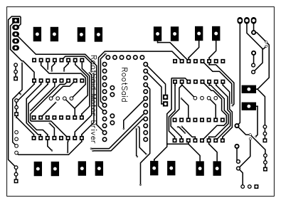
That’s it guys, your layout is now complete. This a dual layer PCB which means the routing is there in both side of the PCB. You can now download the Gerber file and use it to manufacture your PCB from JLCPCB.
Step 4 – Getting High Quality PCB Manufactured
JLCPCB is a PCB manufacturing company with a full production cycle. Which means they start from “A” and finishes with “Z” of PCB manufacturing process. From raw materials to finished products, everything is done right under the roof.

Go to JLCPCBs website and create a free account. Once you have successfully created an account, Click on “Quote Now” and upload your Gerber File.

Gerber File contains information about your PCB such as PCB layout information, Layer information, spacing information, tracks to name a few.
Below the PCB preview, you will see so many options such as PCB Quantity, Texture, Thickness, Color etc. Choose all that are necessary for you.

Once everything is done, click on “Save To Cart”. In the next page, you can choose a shipping and payment option and Check Out Securely. You can either use Paypal or Credit/Debit Card to pay.
Thats it guys. Its Done. The PCB will be manufactured and shipped with in days and will be delivered to your doorstep within the mentioned time period.
Projects using this board from where you can get sample codes will be posted soon. Stay tuned.[AdSense-B]


![Best Arduino Science Projects for Exhibition 2022 [Complete Tutorials Available😎]](https://b1870411.smushcdn.com/1870411/wp-content/uploads/2021/04/DIY-Projects-for-Exhibition-768x432.png?lossy=2&strip=1&webp=1)
Hey Jithin,
I like your tutorial and your PCB. I don’t understand one thing. You are using 4 L293D, each can control 2 Motors – so your PCB is for 8 Motors, right?
Would you explain…?
Not 8 Motors. 2 L293D ICs are piggy backed into one. So there are total of 8 L293D, 2Piggy backed pairs. In effect you have 2 high current L293D ICs. which can control 4 motors independently.