How to make an Arduino Off-Road Robot with Wireless Surveillance Robot with Suspension – Quad Trial
Arduino Off-Road Robot Introduction
Hey guys, I am back with another cool Robot chassis from BangGood. Hope you have gone through our previous projects – Spinel Crux V1 – The Gesture Controlled Robot, Spinel Crux L2 – Arduino Pick and Place Robot with Robotic Arms and The Badland Brawler which we published last month. Looks cool with under glowing lights right?
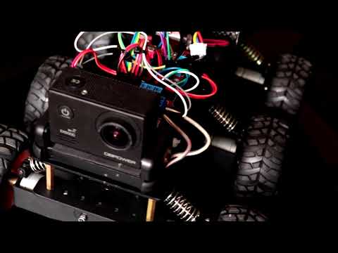
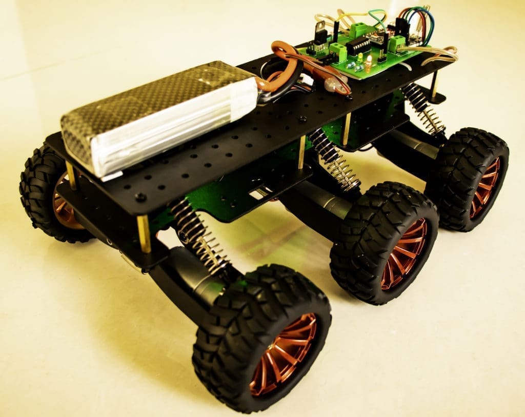
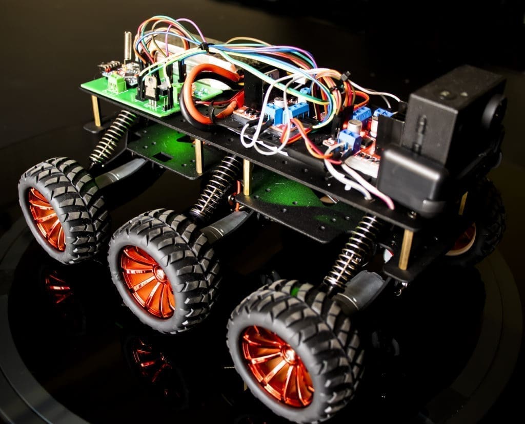
This time I have a rough Terrain Robot with 6 Wheel Drive and dedicated suspension for it to travel over rough terrain. Check it out.
Behold – Robotin -6 – The Off Road Wireless Surveillance 6 Wheel Drive Arduino Robot

Looks Cool right? Watch the below video. You will love it!!
Why not build one for yourself? Here we will learn how to build
We will provide you with the design, code, circuit diagrams and links to buy your own robot kit, chassis and the sensor modules used in this project.
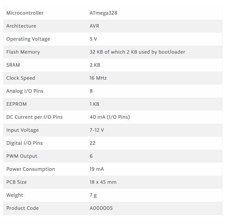
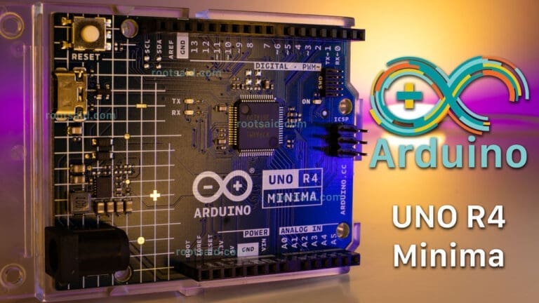
Arduino Nano
In this project we will have to use two micorcontroller – one for the controller which will gather all the sensor data and transmit them to the wireless module and another one on the robot, which will gather data from the receiver module, process them and control robotic arm and the pick and place robot. The Arduino Nano is very small and can easily be fitted on top of the bread board. This can be easily programmed using a PC via USB using Arduino IDE
This board can be powered using the Mini USB port. Through pin 30, we can supply an unregulated voltage source of 6 to 20V or through pin 27, we can provide a regulated power source of 5V. The power selection will be automatically done by the Nano board.
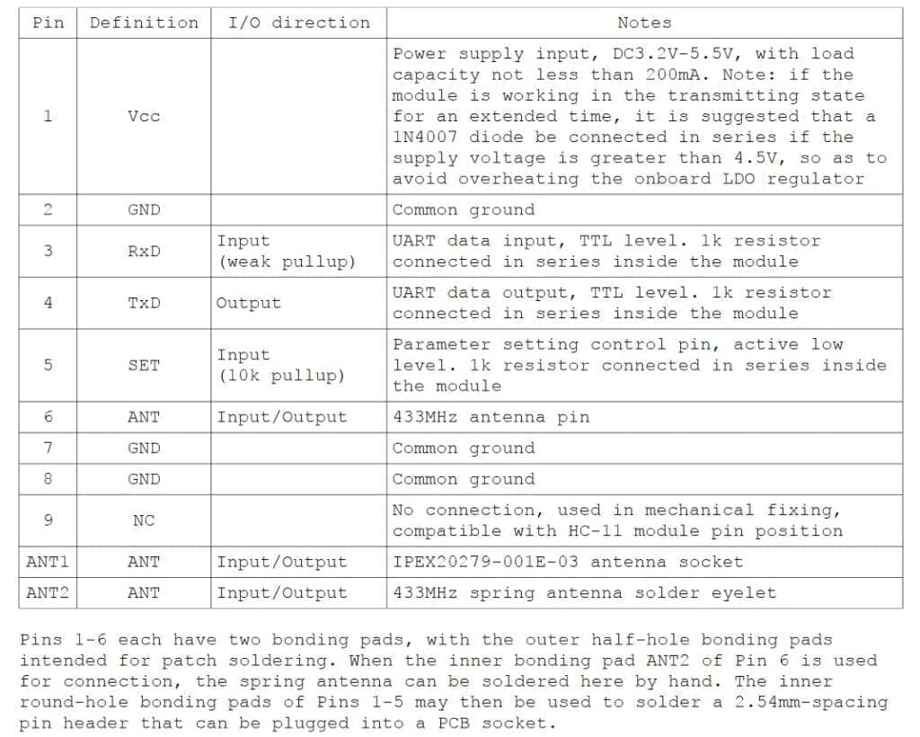
HC12
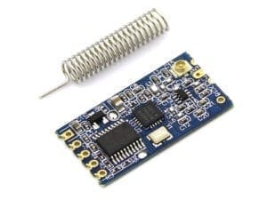
HC 12 is a really cheap long range wireless module which can be used for wireless serial communication over a long distance of upto 1.7 KM. The module is really compact light weight and breadboard friendly which makes this the best wireless controller for our project.
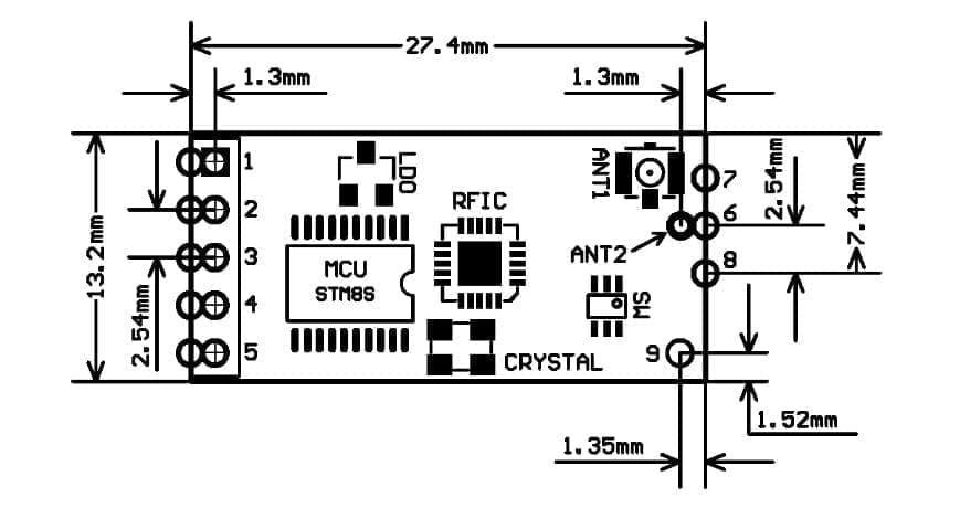
Pinout
Testing HC12 Connection
#include <SoftwareSerial.h>
SoftwareSerial HC12(10, 11); // HC-12 TX Pin, HC-12 RX Pin
void setup() {
Serial.begin(9600); // Serial port to computer
HC12.begin(9600); // Serial port to HC12
}
void loop() {
while (HC12.available()) { // If HC-12 has data
Serial.write(HC12.read()); // Send the data to Serial monitor
}
while (Serial.available()) { // If Serial monitor has data
HC12.write(Serial.read()); // Send that data to HC-12
}
}
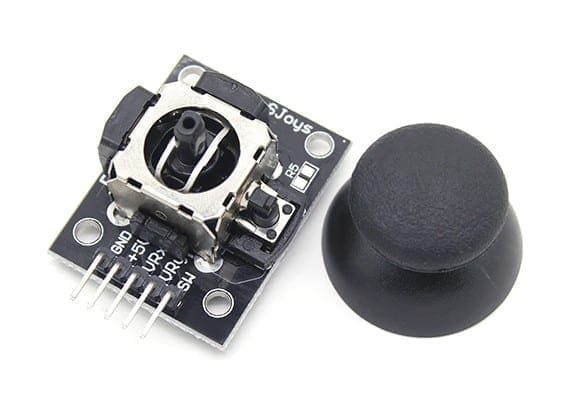
Joystick
This is the most widely used robotic controller which comes with various robot DIY robot kit/robot arm kit that is built to work with arduino. The design is quite simple and is very easy to use. It uses two potentiometers to calculate the motion in the x axis and y axis and a switch to sense the button press.
This can be easily connected to the arduino’s analog pins and read analog values directly.
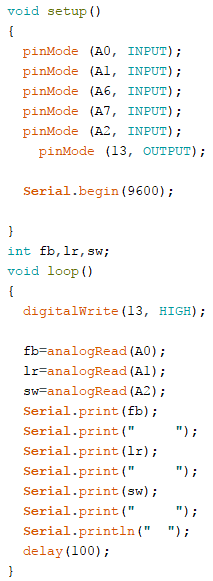
Code for testing the joystick is available down below. Feel free to download/edit it as per your need.

[AdSense-C]Download
Before uploading the main code, make sure your joystick works by using this code. Download the code from the above link. In this example, what we are doing is simply collecting the data analog outputs from the Joystick using the analog pins (A0, A1,A2) of arduino. These values are stored in the variables and are later printed on the serial monitor
We will divide this tutorial into 2 Parts – The Remote Controller and The Robot
1- The Remote Controller
The Transmitter
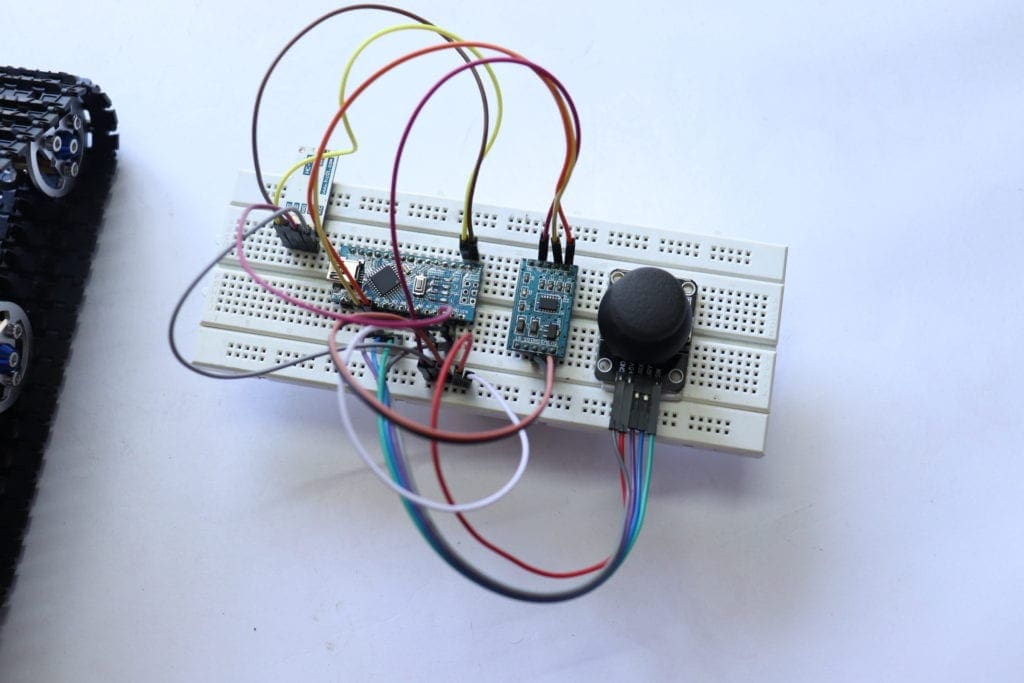
We will use the accelerometer as well as the joystick to control the off-road robot. For now, we will use the joystick button to close the robotic hand. The data from these sensors are transmitted wirelessly to the DIY robot using an HC12 module.
Connections
Arduino – HC12
- 5 Vout – VCC Arduino
- Gnd – Gnd
- 10 – TX
- 11 – Rx
Arduino – Accelerometer
- A0 – X Axis
- A1 – Y Axis
- 5 Vout – VCC Arduino
- Gnd – Gnd
Arduino – JoyStick
- A4 – Switch
- A2 – Forward/Backward of Joy Stick
- A3 – Left/Right of Joy Stick
- 5 Vout – VCC Arduino
- Gnd – Gnd
Code
Simply download the below code using the download link below and upload it to your controller.
2- Arduino Robot Part
Here,
Robot Chassis – DIY Robot Kit
The chassis I used for making this Off-Road Wireless Surveillance 6 Wheel Drive Arduino Robot is something I would like to talk about. I got this kit banggood.com. Not only this one, but they also have so many types of robot frames, motors and almost all the sensors for doing Arduino, raspberry
And the great thing about this kit is they provide all the tools you need to assemble the frame together.
Get your DIY Robot Kit From BangGood.
Power Source
Here we will be using a 12 V power supply for powering up the entire robot. We feed the raw 12 Volt to the LED and the motor driver IC voltage in for motor.
Then we use a regulator to step down the voltage to 5V and feed it to Arduino, HC12 and motor driver.
The H bridge will work only if the Enable Pin is set to Logic 1
One thing to keep in mind while using this IC is, there are two pins where we have to supply the input power. Pin 8 and Pin 16; both are for entirely different purposes. Pin 9 is for driving the motor which can handle a voltage of 6 V to 30 Volt and Pin 16 which will power up the IC for the internal circuit. Under no circumstances, you should not interchange these two pins or it may burn off the chip.
The Motor Driver
You can drive the DC motors using a good motor driver IC which can provide you enough current to drive all the 6 motors. In this project, I will be using Dual H Bridge Motor Driver IC – L293D which can control two servo motors at a time. Since we are using 6 High-Speed DC motors, which will take a considerable amount of current, I decided to piggyback two L293Ds together. Piggybacking is the process of connecting two motor driver ICs in parallel that will double the output current for the motors. Check out the below link to know more about Piggybacking L293D.
For more details on driving DC motors using L293D IC click here.
Connections
Simply connect all the components as shown below.
We will be powering the Arduino with a 5V power bank and use the 5 V Vout of the
Arduino – HC12
- 5 Vout – VCC Arduino
- Gnd – Gnd
- 10 – TX
- 11 – Rx
Arduino – L293D or L298N
- D2 – Right Motor A
- D3 – Right Motor B
- D4 – Left Motor A
- D7 – Left Motor B
- D5 – Enable Pin of Right Motor (For Speed Control)
- D6 – Enable Pin of Left Motor (For Speed Control)
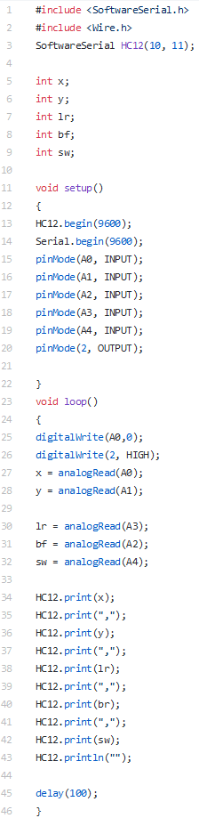
The Code
Upload the below code to your Off-Road Wireless Surveillance 6 Wheel Drive Arduino Robot.
#include <SoftwareSerial.h>
#include <Wire.h>

SoftwareSerial HC12(10, 11);

int lr,x,y;
int bf;
int sw;
String input;
int boundLow;
int boundHigh;
const char delimiter = ',';

void setup() {

Serial.begin(9600);
HC12.begin(9600);

pinMode (2, OUTPUT);
pinMode (3, OUTPUT);
pinMode (4, OUTPUT);
pinMode (5, OUTPUT);
pinMode (6, OUTPUT);
pinMode (7, OUTPUT);
}


void loop() {

  if(HC12.available())
  {
  input = HC12.readStringUntil('n');
  if (input.length() > 0)
      {
        Serial.println(input);

       boundLow = input.indexOf(delimiter);
        x = input.substring(0, boundLow).toInt();

        boundHigh = input.indexOf(delimiter, boundLow+1);
        y = input.substring(boundLow+1, boundHigh).toInt();

        boundLow = input.indexOf(delimiter, boundHigh+1);
        lr = input.substring(boundHigh+1, boundLow).toInt();

        boundHigh = input.indexOf(delimiter, boundLow+1);
        bf = input.substring(boundLow+1, boundHigh).toInt();

        sw = input.substring(boundHigh+1).toInt();

delay(10);

}

//Robot Movement
if (bf <= 50)
{
backward();
}
else if (bf >= 900)
{
forward();
}


else if (lr <= 50)
{
right();
}
else if (lr >= 900)
{

left();
}
else
{
stop();
}
}
}

void forward() {
analogWrite(5, 255);
analogWrite(6, 255);

digitalWrite(2, LOW);
digitalWrite(3, HIGH);
digitalWrite(4, LOW);
digitalWrite(7, HIGH);
Serial.println(" Moving Forward");
}

void backward() {
analogWrite(5, 255);
analogWrite(6, 255);

digitalWrite(2, HIGH);
digitalWrite(3, LOW);
digitalWrite(4, HIGH);
digitalWrite(7, LOW);
Serial.println(" Moving Backward");
}

void stop() {
analogWrite(5, 0);
analogWrite(6, 0);

digitalWrite(2, LOW);
digitalWrite(3, LOW);
digitalWrite(4, LOW);
digitalWrite(7, LOW);
Serial.println(" STOP ");
}

void right() {
analogWrite(5, 255);
analogWrite(6, 50);

digitalWrite(2, LOW);
digitalWrite(3, HIGH);
digitalWrite(4, LOW);
digitalWrite(7, HIGH);
Serial.println(" Moving Left");
}

void left() {
analogWrite(5, 50);
analogWrite(6, 255);

digitalWrite(2, LOW);
digitalWrite(3, HIGH);
digitalWrite(4, LOW);
digitalWrite(7, HIGH);
Serial.println(" Moving Right");
}

void backright() {
analogWrite(5, 255);
analogWrite(6, 50);

digitalWrite(2, LOW);
digitalWrite(3, HIGH);
digitalWrite(4, LOW);
digitalWrite(7, HIGH);
Serial.println(" Moving Left");
}

void backleft() {
analogWrite(5, 50);
analogWrite(6, 255);

digitalWrite(2, LOW);
digitalWrite(3, HIGH);
digitalWrite(4, LOW);
digitalWrite(7, HIGH);
Serial.println(" Moving Right");
}
Lets Ride!!!
Once the code is uploaded to your Off-Road Wireless Surveillance 6 Wheel Drive Arduino Robot, you can connect your robot to a 12 V power source and your robot wireless controller to a 5V power source.
Whats next?
This is just a beginning. We, the RootSaid group is working on a wireless control glove that can be used to control the whole robot, including the robotic arm. But there is something cool about this glove.
This glove can detect hand gestures WITHOUT Flex sensor. Yes you heard that right. Want to find out more? Be a part of rootsaid.
Subscribe RootSaid Website by simply entering your Email ID below. You will receive notification whenever the tutorial is available for you to tinker with.


Hi, we just bought a robot. We want to improve our robot functionality.
We’d like to check with you if you can help to add program like voice commands and songs + movements into our existing robot. Thanks