Making a DIY Soldering Fume Extractor with an Adjustable Lighting System
Introduction to Soldering Fume Extractor
We all love Soldering dont we? Creating our own PCB for our project is fun, but there are a few things that we should take care of while we solder the components into it. During soldering, we are exposed to lead. Also, If we breathe in the fumes, it can cause long-term health issues, including digestive issues, memory and concentration issues, muscle and joint pain, etc. In addition to that, soldering components onto the circuit board puts strain on your eyes, and doing so in dim lighting can eventually cause permanent damage to your eyesight.
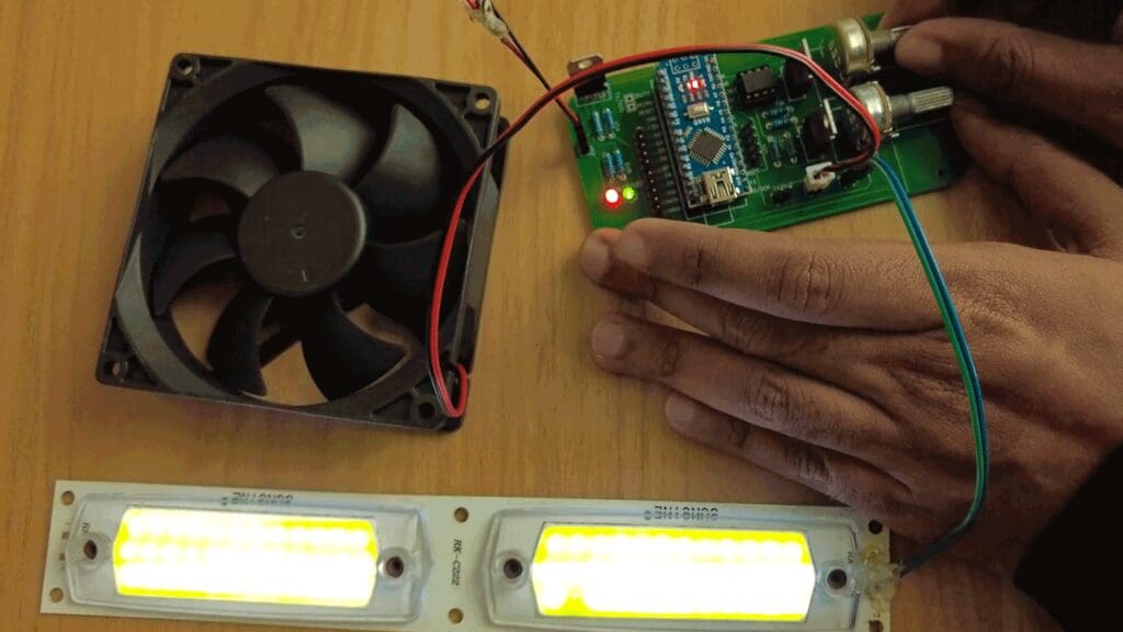
So it is very important to have sufficient light and a fume extractor to get rid of the smoke while soldering! Using a fume extractor will keep you and those around you safe from potentially harmful fumes. In this video, we will be making a soldering fume extractor using an old PC fan and an adjustable lighting system with this 12V LED strip.
So let’s start with the circuit! I used Altium designer to draw the circuit and design the PCB.
The Circuit
Altium is a PCB designer that can be used to create simple PCBs for hobby projects or complex, multi-layered PCBs for industrial use. It’s easy to create our own PCBs using Altium. If you are a DIY electronics enthusiast, you are gonna love it! Altium Subscription includes Altium 365 which lets you design, share and manufacture your project in one place. Secure Centralized Cloud Storage lets you share designs and ideas with teammates or clients.
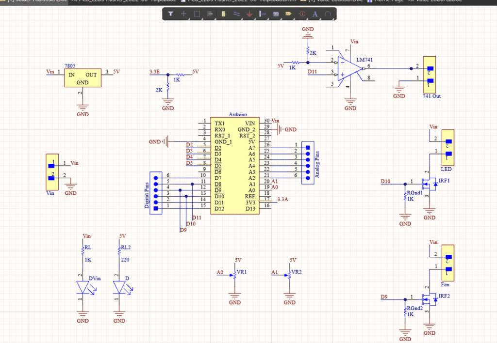
So we basically have an Arduino Nano which is the brain of this project and of course you can use any Arduino board. The input voltage is connected to a 7805 voltage regulator which will convert the VIN to a steady 5V DC supply. There are two potentiometers here that are connected to the 5V which will act as voltage dividers and the output of the pots are connected to analog pins A0 and A1 respectively.
Here are two MOSFETs that are configured to work as switches, which can be switched on by turning on pin 9 and pin 10 of Arduino. Here I would like to point out that Pin 9 and 10 are PWM pins which means we can feed PWM signals to the MOSFETs.
And here you can see an LM 741 comparator IC which can be used to drive any additional devices that you want. Basically, this is the whole circuit.
PCB Layout
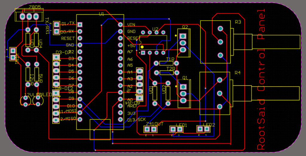
Once the circuit was finished and tested, I designed a compact PCB using Altium, where I can fix all the components neatly. Here you can see routing is on both sides of the board which means it is a dual-layer PCB.
Getting PCB Done
I ordered PCB from PCBWay. PCBWay is a PCB manufacturer specializing in PCB prototyping, low-volume production, and neat and tidy PCB assembly. If you are interested in making your own PCBs for your project, check out the link below. You can get a 5-dollar discount when you sign up using the link below and get an additional 5-dollar discount at the checkout by providing the coupon code PCBWayLab.

To order your PCB from PCBWay, go to the PCBWay website and fill in the basic board details in the instant order form. From there you will be directed to a form where you can provide more elaborate board details. Update your board information in the PCB specification screen. On the next screen, you should be able to upload your Gerber file and submit it for review. Once the review is completed, all that is left is to add to the cart, make payment, and wait for your PCBs to arrive.
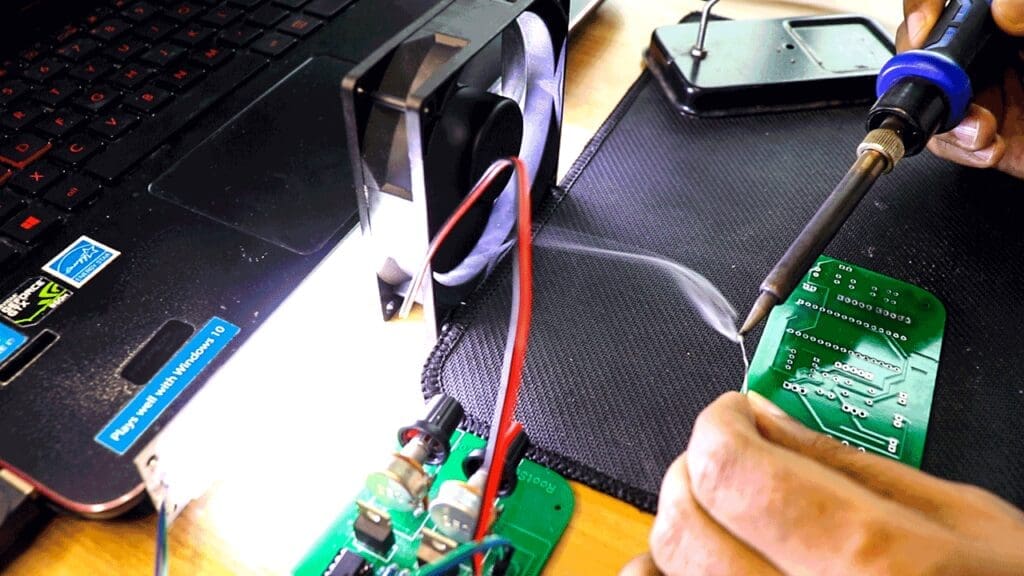
Once you get all the components and the PCB, it’s time for you to solder them together. Solder all the components onto the board and make sure to check the polarity of the components. After soldering the PCB looks like this.
Coding
Now, let’s start coding. This is the code we will be uploading to our Arduino. Well, it looks pretty simple, right? Well, it is simple!
const int ledPin =  13;
const int light = 9;
const int fan = 10;
int pot1 = 0;
int pot2 = 0;

void setup() {

  pinMode(ledPin, OUTPUT);
  pinMode(A0, INPUT);
  pinMode(A1, INPUT);
  Serial.begin(9600);
}

void loop() {

  pot1 = map(analogRead(A0),0,500,0,255);
  pot2 = map(analogRead(A1),0,500,0,255);
  analogWrite(light, pot1);
  analogWrite(fan, pot2);
  delay(50);
  Serial.println(pot1);
  Serial.println(pot2);
  Serial.println("");
}
First, we are declaring some variables and assigning them to the pins that we will be using in this project. Inside the setup function, we are declaring the pin mode, basically telling the Arduino whether they are input pins or output pins.
In the loop function, we are taking the analog readings of the two pots and we are Mapping them to a value between 0 and 255. In the next line, we are outputting PWM signals with values that we generated from the Previous lines to turn on and off the MOSFETs that are connected to the Arduino Pins 9 and 10.
This way, we can control the brightness of the LED strip and control the speed of the fan just by turning the potentiometer. You can connect this fan to a pipe or an outlet and make sure the fumes don’t stay inside the room.
That’s it guys, if you have any doubts about this project, please do ask in the comments. If you want more videos like this, make sure you subscribe to our channel.