Spinel Crux – Gesture Controlled Robot for Wireless Surveillance – Part 2
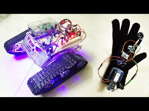
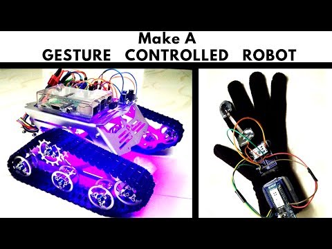
This is the second part of the Spinel Crux Tutorial – Gesture Controlled Robot for wireless surveillance. In this series, we will build a robot which can travel through rough terrain that can be controlled using hand gestures.
Gesture Controlled Robot Tutorial
To control the robot, we will be using the control gloves, which will have an accelerometer and a flex sensor to control the status and the direction it should move. The flex sensor activates the robot and the tilt of the accelerator determines the direction it should move.
Video Demo
Click the Subscribe YouTube button below for Demo and Complete Tutorial
In the previous part of this series, I showed you how to build the control glove of our Gesture Controlled Robot using accelerometer, flex sensor and an Arduino. We will be using this gloves to control the Gesture Controlled Robot we will be building in this tutorial. If you haven’t gone through the first part and don’t have a control glove, take a look at the previous post by clicking the link below.
Gesture Controlled Robot for Wireless Surveillance – Part 1
Spinel Crux – Gesture Controlled Robot for Wireless Surveillance – Tutorial Part 1
First, let us take a look at the components of the Spinel Crux.
Part 1
- Gloves
- Accelerometer
- Flex sensor
- Any Arduino Board with Wi-Fi connectivity
Part 2
- Robot chassis
- L293D motor driver
- Raspberry Pi or another Arduino ( for controlling the robot)
- Breadboard
- Resistor
Before going through the tutorial and building the Gesture Controlled Robot, let us take a closer look at the components we are using in this project.
Video Tutorial Released
Robot Chassi – DIY Smart Robot Tank Chassis Kit
I got this kit banggood.com. Not only this one, they have so many types of robot frames, motors and almost all the sensors for doing arduino, raspberry pi and other electronics and hobby projects.
You will get all these things for a cheap price with really fast and quality shipping.
And the great thing about this kit is they provide all the tools you need to assemble the frame together.
Get your DIY Kit From BangGood

These are some of the best robot chassis available for you to build this project. Check out the link below.
http://bestonlinedeals.today/best-robot-chassis/
L293D
We use a motor driver to drive DC Motors in the embedded project or say for example Robotics project where you cannot drive a motor directly using GPIO pin output of Microcontroller as it doesn’t have the power to run a motor. So we normally use motor drivers like L293D. I will explain how it works
Here I have a pin diagram of L293D. As you can see it has 16 pins. First pin and pin number 9 are enable pins. When you give the power to enable one (on the left side) all the pain on the left side gets activated and while when you provide a 5 V to enable 2 (on the right side), all the pins on the right side gets enabled.
Pin number 7, 2, 15 and 10 acts as the input pins to control the motor, while pin number 3, 6 14 and 11 acts as output where we connect the motor. Pin number 4, 5, 12 and 13 will be grounded. Pin number 8 is the pin to which you have to give the power to run the motor so if you give a 9-volt power supply, the motor run with a 9V power. Pin number 16 is the power for your L293D to work. Make sure that you give 5 volts to pin 16.
Follow this link to know more about H-Bridge and L293D Motor Driver.
Now let us start building our Gesture Controlled Robot. I will show you how to build one using Raspberry Pi.
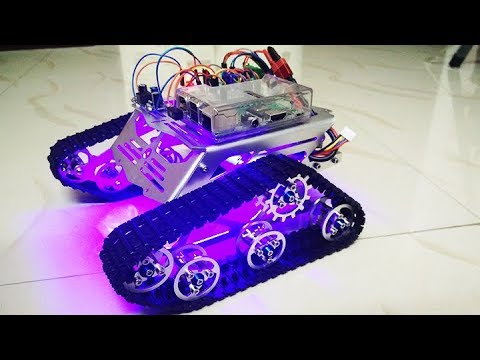
Step 1 – Setting up the Chassis of Spinel Crux
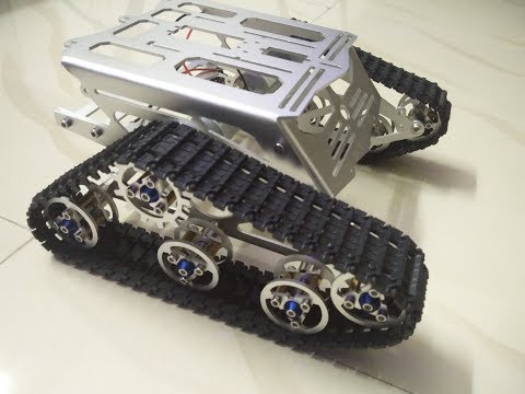
The first thing to do is set up the chassis. Let us take a closer look at the RC Tank kit. There are mainly 4 plates in this kit and all are made of aluminum alloy. There are two wheel mounting plate where we connect the driving wheels, the non-driving wheels and the DC motor. This DC motor is connected to the driving wheels using a metal coupler and the driving wheel is connected to the nondriving wheels using these tracks.
There is a bottom plate that connects the mounting plate where you can conveniently load your battery or motor driver. The top plate acts as the roof and gives this rover an awesome look. There is plenty of space on the plates and lots of mounting points where you can screw down and fix your microcontroller, sensors or actuators without modification. Check out the below video to start assembling
DIY Smart Robot Tank Chassis Kit Assembling
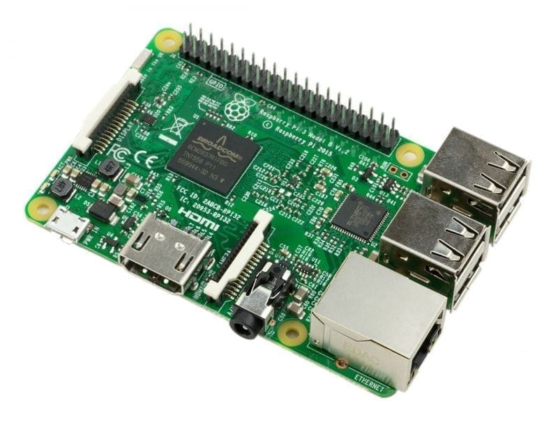
Step 2 – The Raspberry Pi
As you know, Raspberry Pi is an awesome versatile single board computer which can be used for various purposes like robotics, home automation, official use etc.
Get your Raspberry Pi from Here
Now power it up, fire up your terminal and create a password for the user ‘pi’ by executing the command
sudo passwd pi
Now perform and update and upgrade by running
sudo apt update -y && sudo apt upgrade -y
Step 3 – The Network
Connect your Spinel Crux Raspberry Pi to your WiFi network (same WiFi network in which the control glove is connected) and make sure it is connected by checking whether it is getting an IP address from the switch/router.
Take a note of the IP address of our Gesture Controlled Robot. This is the IP Address which you should enter in the “”IPAddress ip(192, 168, 1, 3);”” in the Arduino Code of the previous step.
Step 4 – The Connections
Power
Here we mainly have 2 components to power up – The Raspberry Pi and the DC Motors.
We can provide a voltage of 5V to the Raspberry Pi via Micro USB port and a voltage of 12 V to the L293D which will power the DC motor.[AdSense-C]
Here I will be using an 11.1 V LiPo battery to power the whole Robot. A voltage regulator will be used to step down this voltage to 5 V power up the Raspberry Pi.
DC Motor Driver
You can drive the DC motors using using a good motor driver IC. In this project, I will be using Dual H Bridge Motor Driver IC – L293D which can control two servo motors at a time.
For more details on driving DC motors using L293D IC click here. If you are new to this, it is better to go through this before proceeding to the next step to get a better understanding of the project.
Get your L293D Driver Board now.
Circuit
Now you can connect GPIO pins to Driver Board
- GPIO 11 to Motor A input 1
- GPIO 33 to Motor A input 2
- GPIO 15 to Motor B input 1
- GPIO 13 to Motor B input 2
- GPIO 31 to LED Trigger (Optional – Coming Soon)
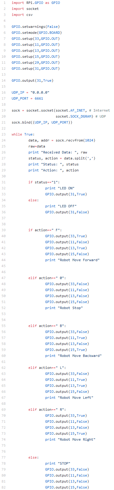
Step 5 – The Code
The python code for the Raspberry Pi is available on GitHub and you can download it from the link below.
[AdSense-A]Download
Code explained
The code is written in python and is very simple and easy to understand. Once you download the code and start running, it will listen on port 6661 for UDP packets.
When it receives the packet, the command string will be extracted and is stored in a variable.
This variable is then passed through some conditional statements and is then used to run the motor in the desired direction.
Start Driving
Everything is all set and you are now good to go. Power up your Control Glove and your Raspberry Pi. Run the script in our Gesture Controlled Robot, put on your gloves and start riding.
Wait… The Camera
Once you have done till this part, you can now connect your camera and setup motion in your raspberry pi. Follow the below link to set it up
Now fire up your browser and enter the URL as mentioned in the above post. You should be able to see the live footage.
If you have any trouble in following the tutorial or you are stuck somewhere, feel free to ask it in the comments.
[AdSense-B]
Rate the Project
Did you find this useful? Help us to improve by rating this page.