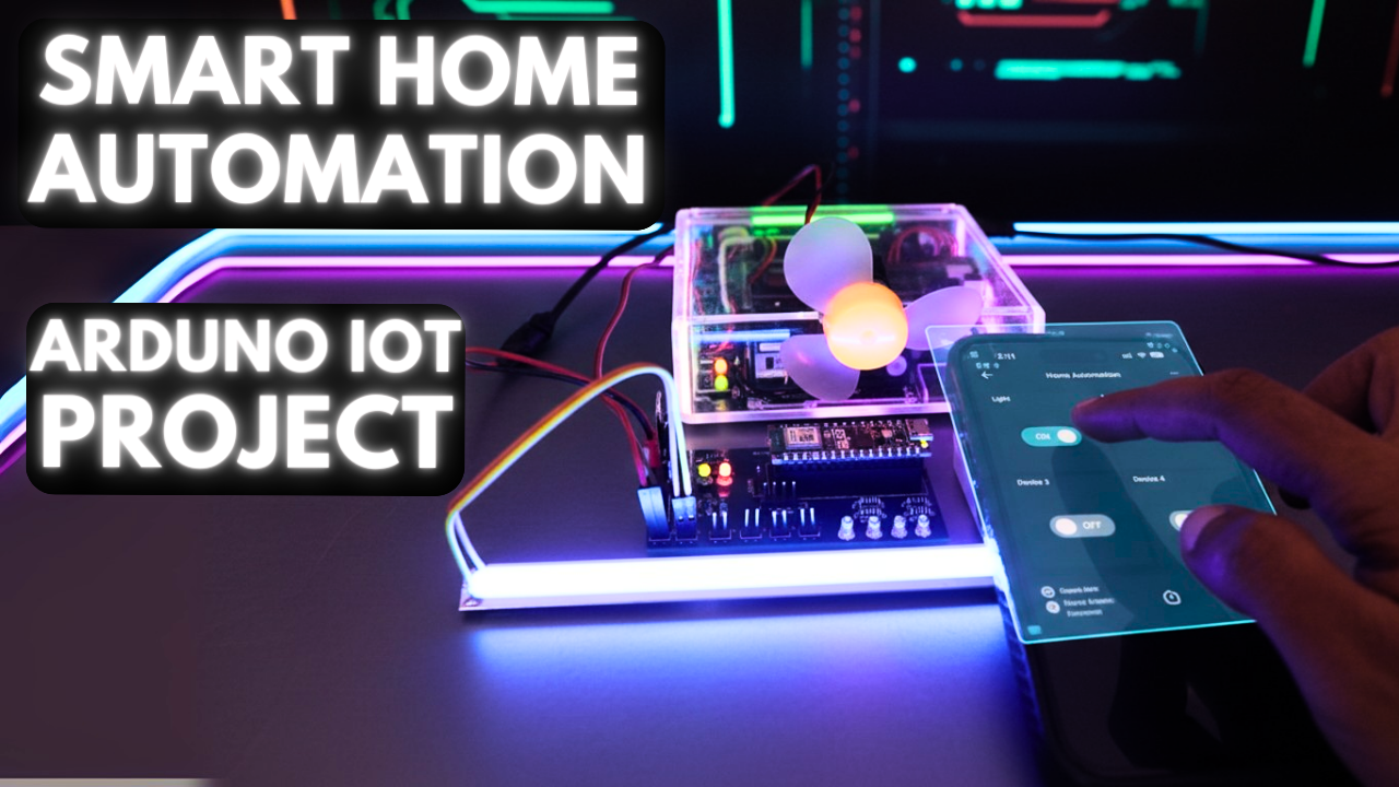
Home Automation with Arduino Nano ESP32 and Arduino IoT Cloud
Smart homes are no longer a futuristic dream—they are here, and they’re easier to build than ever before. With the power of Arduino Nano ESP32 and Arduino IoT Cloud, you can control lights, appliances, and other devices from anywhere in the world using just your phone or computer.

In this article, we’ll walk step by step through creating a home automation system using Arduino Nano ESP32. We’ll explain the hardware setup, IoT Cloud configuration, and the code that makes it all work. By the end, you’ll have a complete, functional system ready to expand with your own ideas.
Why Arduino Nano ESP32?
The Arduino Nano ESP32 is a compact yet powerful board based on the ESP32 microcontroller. It’s ideal for IoT projects because of its built-in Wi-Fi and Bluetooth. Unlike the classic Arduino UNO, which often requires external modules for connectivity, the Nano ESP32 integrates everything into a tiny board that fits easily into any project.

Key advantages of Arduino Nano ESP32:
- Built-in Wi-Fi and Bluetooth support
- Dual-core processor for faster performance
- Smaller and more compact compared to Arduino UNO
- Lower power consumption, ideal for IoT applications
- Native compatibility with Arduino IoT Cloud
This makes it a natural choice for modern home automation systems.
Components You’ll Need
To get started, gather the following components:
- Arduino Nano ESP32 – the main controller board
- Breadboard and jumper wires – for prototyping connections
- MOSFETs or Relays – for controlling devices (MOSFETs for DC loads, relays for AC loads)
- LEDs with resistors – for testing outputs
- USB cable / power supply – to power your board
Optional: If you plan to control mains-powered appliances (like lights or fans), use relay modules with proper isolation to ensure safety.
Circuit Design
The circuit is straightforward. Here’s how it works:
- The Nano ESP32 GPIO pins are connected to MOSFET gates or relay inputs.
- Each MOSFET or relay then switches a connected device ON or OFF.
- For demonstration, we connect LEDs to different pins to simulate devices.
Here’s the correct pin mapping for this project:
| Device Type | Cloud Variable | GPIO Pin |
|---|---|---|
| Relay/MOSFET 1 | Light | 9 |
| Relay/MOSFET 2 | Fan | 8 |
| Device 1 (LED/Relay) | device1 | 10 |
| Device 2 (LED/Relay) | device2 | 11 |
| Device 3 (LED/Relay) | device3 | 12 |
| Device 4 (LED/Relay) | device4 | 13 |
This means whenever you toggle a switch in the IoT Cloud, the corresponding GPIO pin changes state and controls the device.
Setting Up Arduino IoT Cloud
The Arduino IoT Cloud is a web platform that allows you to connect your hardware to the internet and control it remotely.
Follow these steps to set up:
- Log in to your Arduino IoT Cloud account.
- Create a new Thing and add your Arduino Nano ESP32 as the device.
- Define four Boolean variables:
device1device2device3device4
These represent the ON/OFF state of four devices.

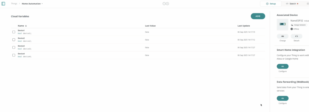
- Set these variables to READ/WRITE so they can be controlled from the dashboard.
- Build a Dashboard in Arduino IoT Cloud and add four toggle switches linked to each variable.

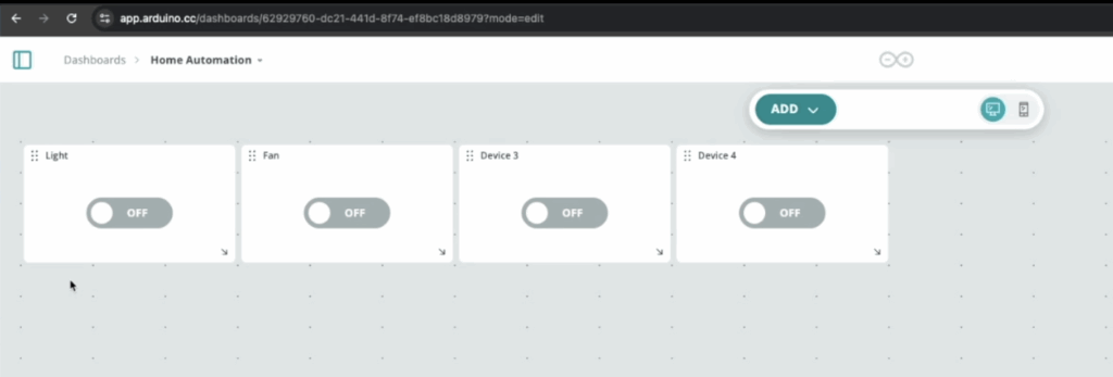
Now you have a virtual control panel ready.
The Code Explained
When you link your device with IoT Cloud, Arduino automatically generates the basic code structure. Below is the sketch updated with the correct pin assignments.
/*
  Sketch generated by the Arduino IoT Cloud Thing "Untitled"
  https://create.arduino.cc/cloud/things/b8a42955-f09f-4ac2-bae8-ab533931ce9c

  Arduino IoT Cloud Variables description

  The following variables are automatically generated and updated when changes are made to the Thing

  bool device1; --> This will be light
  bool device2; --> This will be fan
  bool device3; --> Any device 3
  bool device4; --> Any device 4

  Variables which are marked as READ/WRITE in the Cloud Thing will also have functions
  which are called when their values are changed from the Dashboard.
  These functions are generated with the Thing and added at the end of this sketch.
*/

#include "thingProperties.h"

void setup() {
  // Initialize serial and wait for port to open:
  Serial.begin(9600);
  // This delay gives the chance to wait for a Serial Monitor without blocking if none is found
  delay(1500);
  pinMode(9, OUTPUT);
  pinMode(8, OUTPUT);
  pinMode(12, OUTPUT);
  pinMode(13, OUTPUT);
  // Defined in thingProperties.h
  initProperties();

  // Connect to Arduino IoT Cloud
  ArduinoCloud.begin(ArduinoIoTPreferredConnection);

  /*
     The following function allows you to obtain more information
     related to the state of network and IoT Cloud connection and errors
     the higher number the more granular information you’ll get.
     The default is 0 (only errors).
     Maximum is 4
 */
  setDebugMessageLevel(2);
  ArduinoCloud.printDebugInfo();
}

void loop() {
  ArduinoCloud.update();
  // Your code here


}

/*
  Since Device1 is READ_WRITE variable, onDevice1Change() is
  executed every time a new value is received from IoT Cloud.
*/
void onDevice1Change()  {
  if (device1 == true) {
    digitalWrite(9, HIGH);
  }
  else
  {
    digitalWrite(9, LOW);
  }
}

/*
  Since Device2 is READ_WRITE variable, onDevice2Change() is
  executed every time a new value is received from IoT Cloud.
*/
void onDevice2Change()  {
  if (device2 == true) {
    digitalWrite(8, HIGH);
  }
  else
  {
    digitalWrite(8, LOW);
  }
}

/*
  Since Device3 is READ_WRITE variable, onDevice3Change() is
  executed every time a new value is received from IoT Cloud.
*/
void onDevice3Change()  {
  if (device3 == true) {
    digitalWrite(12, HIGH);
  }
  else
  {
    digitalWrite(12, LOW);
  }
}

/*
  Since Device4 is READ_WRITE variable, onDevice4Change() is
  executed every time a new value is received from IoT Cloud.
*/
void onDevice4Change()  {
  if (device4 == true) {
    digitalWrite(13, HIGH);
  }
  else
  {
    digitalWrite(13, LOW);
  }
}
[Scene 4 – Coding Part]
This sketch is designed to connect an Arduino Nano ESP32 to the Arduino IoT Cloud so you can remotely control devices. At the top, the variables device1, device2, device3, and device4 are automatically generated by the IoT Cloud platform. Each variable corresponds to a toggle switch in your cloud dashboard.
In the setup() function, the code initializes serial communication for debugging, sets pins 9, 8, 10, 11, 12, and 13 as outputs (to drive LEDs, MOSFETs, or relays), and then connects the board to the IoT Cloud using ArduinoCloud.begin(). Debugging is enabled so you can monitor the connection state in the Serial Monitor.
The loop() function simply calls ArduinoCloud.update(), which keeps the device synchronized with the cloud. Whenever you change the state of a switch in your IoT dashboard, the cloud updates the linked variable (device1–device4), and the corresponding function (onDeviceXChange) is triggered. Each of these functions checks if the variable is true (ON) or false (OFF), and then sets the matching digital pin HIGH or LOW, effectively switching the device on or off. In short, this code establishes a direct link between your IoT Cloud dashboard and your physical devices, allowing you to control them remotely in real time.
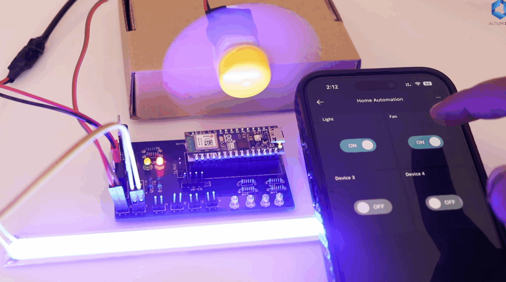
Testing the System
Once the code is uploaded, open the Serial Monitor to confirm Wi-Fi and IoT Cloud connection.
- Toggle
device1in the dashboard → LED or relay connected to pin 10 turns ON. - Toggle
device2→ LED or relay on pin 11 responds. - Toggle
device3anddevice4→ devices on pins 12 and 13 respond instantly. - If you’re using pins 9 and 8 for MOSFETs or relays, they can handle other loads in the same way.
At this point, your smart home system is fully operational.
Arduino UNO vs Arduino Nano ESP32 for Home Automation
| Feature | Arduino UNO R4 WiFi | Arduino Nano ESP32 |
|---|---|---|
| Connectivity | Wi-Fi only | Wi-Fi + Bluetooth |
| Size | Standard UNO form | Much smaller (Nano size) |
| Logic Voltage | 5V | 3.3V |
| Processing Power | Single-core | Dual-core |
| Expansion | Compatible with many shields | Compact, fits small enclosures |
| Best For | Beginners, larger prototypes | Compact IoT projects, advanced setups |
Advantages of Using Arduino IoT Cloud
Using Arduino IoT Cloud makes automation much easier compared to custom server setups. Some benefits include:
- No server needed – Cloud handles communication.
- Cross-device control – Works on smartphones, tablets, and PCs.
- Real-time updates – Instant ON/OFF control.
- Expandable – Add sensors, dashboards, and multiple devices.
- Secure communication – Encrypted connection via Arduino’s cloud services.
Possible Extensions
Once your basic automation is working, you can expand it with creative ideas:
- 🌡 Add temperature sensors to monitor room conditions.
- 🌞 Automate lights using light sensors.
- 📅 Create schedules in the IoT Cloud for timed operations.
- 🎤 Integrate with Alexa or Google Assistant for voice control.
- 📊 Log energy usage by adding current sensors.
Common Issues and Solutions
- Device not connecting to Wi-Fi: Double-check SSID and password in your thingProperties.h file.
- Pins not responding: Remember that Nano ESP32 uses 3.3V logic. Ensure relays are 3.3V compatible or use level shifters.
- Cloud dashboard unresponsive: Verify the device is online in the IoT Cloud panel.
Conclusion
With just a few components and the Arduino Nano ESP32, you can build a reliable and compact home automation system. The Arduino IoT Cloud makes it easy to control devices remotely, monitor status, and expand functionality.
This project demonstrates how IoT can be simple, accessible, and fun to build. Whether you start with LEDs or go all the way to controlling your home appliances, the Nano ESP32 is a great platform to make your smart home a reality.
👉 Ready to take it further? Try adding sensors, voice assistants, or custom dashboards and see how versatile this system can be.