OSI Model Explained – Communication Model
Suppose we have two systems A and B and they want to communicate with each other, the data has to travel from A to B and vice versa. To ensure that this data reaches the receiver from the source, we need to have some rules that guides the communication. These rules are called protocols.[AdSense-C]
These protocols are orderly grouped together and this group is called a model.
OSI (Open Systems Interconnection) communication model is one such commonly used communication model.
OSI Model

OSI is a 7 layer model, each layer has some protocols that processes the data. Each layer communicates with layers above or below it. But working of each layers is independant of other layers which means if we are upgrading any layer, we just have to modify that single layer.
Layer 7 – Application Layer
This is the layer at which the users communicate with the system. This layer deals with Network related Applications in the computer that are used in the network. This layer is responsible for displaying the data or inputting the data. For example browsers like firefox, chrome. Protocols that are running on this layer are HTTP, telnet, FTP etc.
Layer 6 – Presentation Layer
This layer is concerned with the format of the data to be send or received. Here data encryption and compression takes place. Image compression like JPEG and MPEG also takes place at this layer. Protocols that are running on this layer are SSL, TLS
Layer 5 – Session Layer
Creates and maintains session. Suppose we have two applications firefox and telnet running on the same system. Session layer creates 2 seperate, independant sessions and maintains them till they are closed.[AdSense-A]This layer is also responsible for time stamping. Handshaking process takesplace here.
Layer 4 – Transport Layer
This layer manages dataflow control. This layer decides whether to use reliable communication or unreliable communication. TCP and UDP are the two protocols working in that layer. When reliable communication is needed Transport layer uses TCP and when unreliable communication is required this uses UDP.
Reliable communication means, the transmitter should get acknowledgment for every packets send. Only if it gets the acknowledgment, it will send the next packet. In unreliable communication, there is no acknowledgement. And Due to this reason unreliable communication is faster. so realtime applications will be using UDP rather than TCP. Transport layer also creates a port number for the packets send. port number is a number attached with the IP address to identify from which application the packets are coming from.
Layer 3 – Network Layer
This layer is responsible for source and destination IP addressing. This is the layer where the routers operate. Provides connectivity between different nodes outside LAN. This layer also finds the best path for the packet to travel from source to destination.
Layer 2 – Datalink Layer
This layer is responsible of MAC addressing the packets. Switches operates at this layer.[AdSense-C] Provides connectivity between different nodes inside LAN. Protocols like ARP works in this layer.
Layer 1 – Physical Layer
This layer specifies the medium used for transmitting the data from source to destination. Provides physical connectivity between different nodes. This layer also take care of modulation and demodulation. Devices working on this layer are cables, hubs, repeaters etc
In a Nutshell
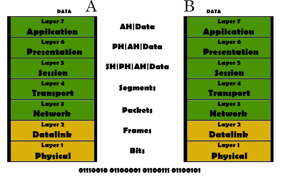
If A has to send a video clip to B, A uses its Application Layer to input the video file. Here, an Application Header will be added to the data. This data will be passed on to the presentation layer where it will be compressed and encrypted. Here a Presentation Header will be added to the data. In the next layer, a session will be established for this data to travel from A to B. In Transport layer, the whole video will be divided into different segments. Depending up on the connection type UPD or TCP Header will be added to each segment. In network layer, network header will be added to each segments one by one and is converted to packets.
The network header contains information about the source and destination IP address and path to the receiver. In the Datalink layer, the datalink header will be added and packets will be converted to frames. The physical layer modulates the signal, converts these signals to 0s and 1s and send this data to B. The reverse thing happens on the receiving side. The physical layer demodulates the signal and passes on to higher layers. The above layers strip of the corresponding headers. The transport layer waits for all the segments of this session and combine them. And in layer 7 B will get the data. This is how a communication system works.