DIY Telepresence Robot for Shopping during COVID 19 Lockdown | Arduino Robotics
I will be showing you how I made a DIY Telepresence Robot using Arduino that can be controlled from a mobile phone, which I used for shopping, buy stuff from nearby shops, pass things to my neighbors and friends house, during this COVID 19 lockdown period while sitting in my home safe and sound, obeying social distancing protocol.

COVID 19 and Social Distancing
As you guys know COVID-19 has become a global threat faced by people all over the world and it is still spreading like wildfire. COVID-19 can only be defeated with peoples coordination.
Social distancing is an important step that will help us to fight against COVID-19. This is done by reducing contact with people who may or may not be infected. So it’s always a better idea to stay in your home as long as possible.
Why I Built Arduino Telepresence Robot?
But we are all human beings, right? We need supplies, buy stuff and sometimes interact with people in one way or the other. So I decided to make a robot for doing all these things on my behalf. A Robot that could go out and buy stuff from nearby shops as well as interact with my neighbours and friends.

In a nutshell, that’s the story behind my DIY Telepresence Robot Arduino. Like always I’ll be giving you complete instructions including the circuit diagram, the PCB files if you want to make a PCB, the codes, and their explanations so that you can make one yourself.
DIY Telepresence Robot Arduino for Shopping during COVID-19 – Video Tutorial
Too lazy to read all these. Well, fret not. We have a complete video tutorial where we explain how we built the robot for shopping during COVID-19 with step by step instructions. Watch the below video.

We are super excited to teach you everything you need to know about Arduino, Robotics, home automation, and other fun stuff. If you are a true fan of Arduino and robotics make sure you check out our channel. There are a lot of DIY tutorials that are gonna be really interesting for you. If you want more project tutorials like this make sure you subscribe to our channel by hitting the subscribe button.
What I used to Build my DIY Telepresence Robot Arduino?
For this project all I needed was a mobile phone, mobile phone stand, an Arduino board with Wi-Fi connectivity, and L293D motor driver IC.
- Arduino Nano 33 IoT – Check it on Amazon
- L293D/L298N Motor Driver IC – Check it on Amazon
- DC Motors – Check it on Amazon
- Robot Chassis – Check Price
- LED – Check it on Amazon
- Soldering Iron – Check it on Amazon
- Terminal Blocks – Check it on Amazon
- Breadboard/PCB
Steps to Make a Telepresence Robot for Shopping
Steps 1 – The Plan – Designing Arduino Telepresence Robot for Shopping
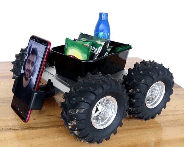
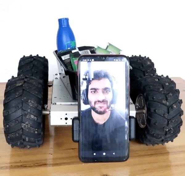
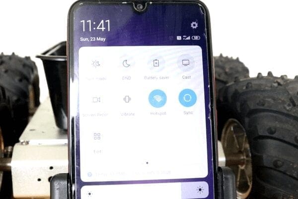
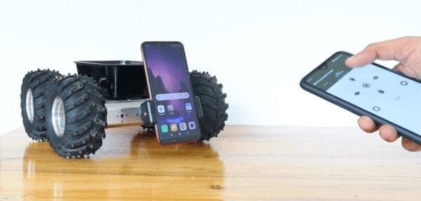
The idea was to fix this mobile phone in front of the robot as shown in the video and Turn On mobile data and mobile hotspot. The Arduino will connect to this mobile hotspot. We will use another mobile phone which will connect to the same hotspot, where we install an app, using which we will send signals to the Arduino and control the robot. To get live video and audio feed, we will be using Skype call or Google meet.
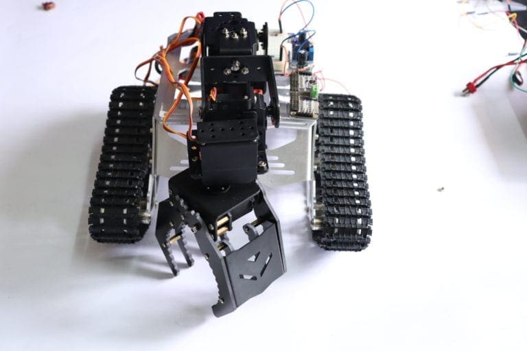
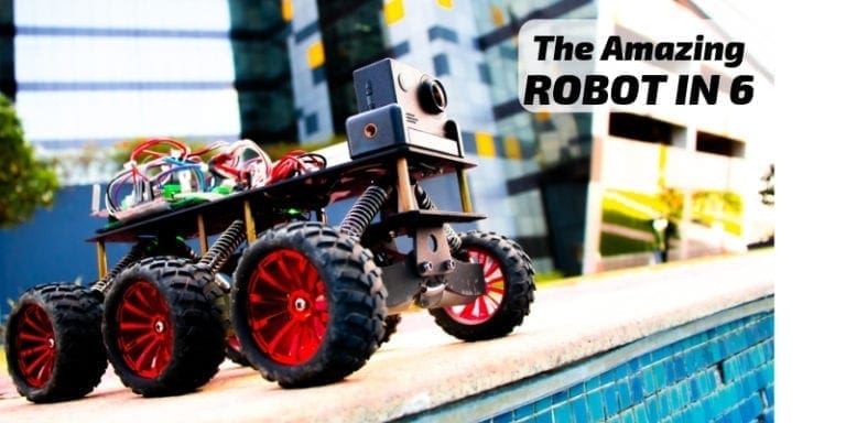
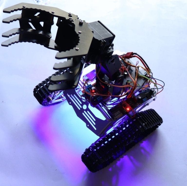
Step 2 – The Robot Chassis
Here I’ll be using this 4 motor-driven robot body. This one is made of aluminium and has a top roof. It has huge tyres which will help it to get over obstacles effortlessly.
Step 3 – Drawing the Circuit for our Telepresence Robot
So I designed a circuit that will connect to the Arduino IoT cloud using our phone’s mobile network, receive data from the cloud, and drive the motors using the motor driver IC. I used Altium designer to draw the circuit and design the PCB. It is a powerful tool that can be used to design and create our own PCBs for our project as well as complex and multi-layer PCBs for industrial use. I will provide the link to the free version in the description. Make sure you check it out!
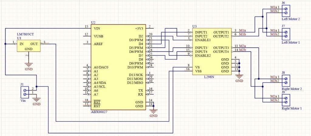
Telepresence Robot using L298N Motor Driver IC

Telepresence Robot using L293D Motor Driver IC

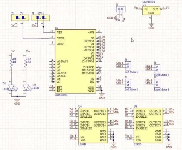
I will be providing voltage input at this point. I decided to go with a 12 volt Lithium polymer. This voltage input is then fed to a 7805 voltage regulator. This voltage regulator converts and regulates voltage between 8 to 30 volt to study 5 volt DC power supply. This 5 volt is then connected to Arduino and l293d motor driver IC. Later, I decided to connect Vin directly to the Arduino Vin pin.
Since I have four Motors, two on either side, I decided to connect two l293d motor driver ICs in parallel. This will double the current and will provide enough to drive four Motors together.
Input for the left motors, that is input 1, input 2 and enable 1 will be connected to D4, D5 and D2 of the Arduino. Whereas input for right motors, that is input 3 input 4 and enable 2 will be connected to D6, D7 and D3 of the Arduino.
This is the circuit. You can try it out on a breadboard and once you are done, you can use it as such for the project or make your own PCB. I personally like PCBs. PCBs are neat and help to get rid of all nasty wires hanging around. Nowadays, it’s not that hard to design and make a PCB for your project. And it’s cool to make your own PCBs for your project right?
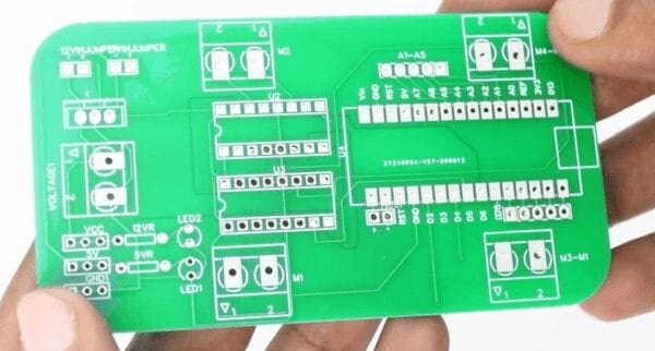
Once the circuit for DIY Telepresence Robot Arduino was finished, I designed a compact PCB using Altium, where I can fix all the components neatly. Here you can see, this is a 4 layer PCB, but components are placed on the top side. And that’s done. Now all you have to do is export the Gerber.
Step 4 – Getting the PCB Done
I ordered PCB from PCBWay. PCBWay is a PCB manufacturer specializing in PCB prototyping, low-volume production, and neat and tidy PCB assembly. To order our PCB from PCBWay, go to the PCBWay website and fill in the basic board details in the instant order form. From there we will be directed to a form where we can provide more elaborate board details.

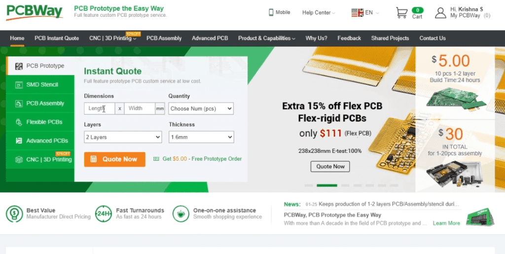
Update the board information in the PCB specification screen. On the next screen, we should be able to upload the Gerber file and submit it for review. Once the review is completed, all that is left is to add to the cart, make payment, and wait for the PCBs to arrive.

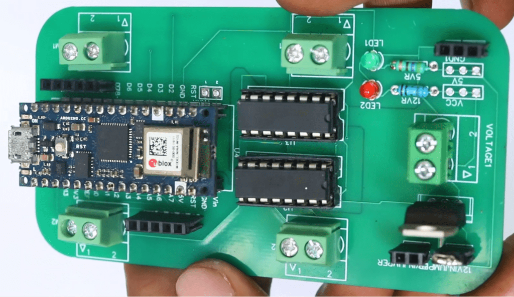
Once we get all the components and the PCB, it’s time for us to solder them together. Solder all the components onto the board and make sure to check the polarity of the components. After soldering the PCB looks like this.

Step 5 – Setting Up WiFi Network
Like I mentioned earlier, this Robot is controlled using an Android Smartphone using WiFi. This is similar to our WiFi Robot using Arduino which I published a month ago.
In order to control our robot, it should be connected to an active WiFi network. You can either use your home WiFi network or as I did, you can create a hotspot on your smartphone which is attached to the robot.

Step 6 – Controlling and Shopping using Telepresence Robot
The app we will be using to control our Robot is called RootSaid WiFi Command Center. This is an App that you can use to create home automation and Robotics projects using WiFi. After installation, open the App, and on the Setup page you can enter the IP and port number of the Robot and in the Robot Controller Tab, you should be able to send commands to Arduino using these tap buttons.
Step 7 – Coding for Shopping
Let’s get down to the software part. In the Arduino, I wrote a code that will connect to the WiFi network created by the mobile phone attached to the robot and will listen to a particular port for incoming packets. Once it receives a command from the mobile phone, it will check the command and drive the robot accordingly.
#include <SPI.h>
#include <WiFiNINA.h>
#include <WiFiUdp.h>

int status = WL_IDLE_STATUS;
char ssid[] = "WiFi Name"; //WiFi Network Name
char pass[] = "Password"; //WiFi Network Password
int keyIndex = 0;
unsigned int localPort = 5005;

char packetBuffer[256];
char  ReplyBuffer[] = "acknowledged";

WiFiUDP Udp;
#include "thingProperties.h"

void setup() {
  pinMode(4, OUTPUT);
pinMode(5, OUTPUT);
pinMode(6, OUTPUT);
pinMode(7, OUTPUT);
pinMode(2, OUTPUT);
pinMode(3, OUTPUT);
  // Initialize serial and wait for port to open:
  Serial.begin(9600);
  // This delay gives the chance to wait for a Serial Monitor without blocking if none is found
  delay(1500);

  // Defined in thingProperties.h
  initProperties();

  // Connect to Arduino IoT Cloud
  ArduinoCloud.begin(ArduinoIoTPreferredConnection);

  /*
     The following function allows you to obtain more information
     related to the state of network and IoT Cloud connection and errors
     the higher number the more granular information you’ll get.
     The default is 0 (only errors).
     Maximum is 4
 */
  setDebugMessageLevel(2);
  ArduinoCloud.printDebugInfo();

    // check for the WiFi module:
  if (WiFi.status() == WL_NO_MODULE) {
    Serial.println("Communication with WiFi module failed!");
    // don't continue
    while (true);
  }

  String fv = WiFi.firmwareVersion();
  if (fv < WIFI_FIRMWARE_LATEST_VERSION) {
    Serial.println("Please upgrade the firmware");
  }

  // attempt to connect to Wifi network:
  while (status != WL_CONNECTED) {
    Serial.print("Attempting to connect to SSID: ");
    Serial.println(ssid);
    status = WiFi.begin(ssid, pass);

    delay(5000);
  }
  Serial.println("Connected to wifi");
  printWifiStatus();

  Serial.println("nStarting connection to server...");
  Udp.begin(localPort);


}

void loop() {
  ArduinoCloud.update();
  // Your code here
   int packetSize = Udp.parsePacket();
  if (packetSize) {
    Serial.print("Received packet of size ");
    Serial.println(packetSize);
    Serial.print("From ");
    IPAddress remoteIp = Udp.remoteIP();
   Serial.print(remoteIp);
    Serial.print(", port ");
   Serial.println(Udp.remotePort());

    int len = Udp.read(packetBuffer, 255);
    if (len > 0) {
      packetBuffer[len] = 0;
    }
    Serial.print("Command Received: ");
    Serial.println(packetBuffer);


 if(strcmp(packetBuffer, "forward") == 0)
    {
mforward();
    }
 else if(strcmp(packetBuffer, "left") == 0)
    {
mleft();
    }
 else if(strcmp(packetBuffer, "right") == 0)
    {
mright();
    }
 else if(strcmp(packetBuffer, "backward") == 0)
    {
mbackward();
    }
else if(strcmp(packetBuffer, "stop") == 0)    {
mstopp();
    }

Serial.println("");
    Udp.beginPacket(Udp.remoteIP(), Udp.remotePort());
    Udp.write(ReplyBuffer);
    Udp.endPacket();
  }

}

void printWifiStatus() {
  // print the SSID of the network you're attached to:
  Serial.print("SSID: ");
  Serial.println(WiFi.SSID());

  // print your board's IP address:
  IPAddress ip = WiFi.localIP();
  Serial.print("IP Address: ");
  Serial.println(ip);

  // print the received signal strength:
  long rssi = WiFi.RSSI();
  Serial.print("signal strength (RSSI):");
  Serial.print(rssi);
  Serial.println(" dBm");
}

void onIPChange() {
  // Do something
}

void mleft()
{
  analogWrite(2, 255);
  analogWrite(3, 255);

  digitalWrite(5,LOW);
  digitalWrite(4,HIGH);
  digitalWrite(6,LOW);
  digitalWrite(7,HIGH);
  Serial.println("Forward");
}

void mright()
{
  analogWrite(2, 255);
  analogWrite(3, 255);

  digitalWrite(5,HIGH);
  digitalWrite(4,LOW);
  digitalWrite(6,HIGH);
  digitalWrite(7,LOW);
  Serial.println("Backward");
}

void mforward()
{
  analogWrite(2, 250);
  analogWrite(3, 250);

  digitalWrite(5,LOW);
  digitalWrite(4,HIGH);
  digitalWrite(6,HIGH);
  digitalWrite(7,LOW);
  Serial.println("Left");
}
void mbackward()
{
  analogWrite(2, 250);
  analogWrite(3, 250);

  digitalWrite(5,HIGH);
  digitalWrite(4,LOW);
  digitalWrite(6,LOW);
  digitalWrite(7,HIGH);
  Serial.println("Right");
}

void mstopp()
{
  digitalWrite(5,LOW);
  digitalWrite(4,LOW);
  digitalWrite(6,LOW);
  digitalWrite(7,LOW);

}
This is my code. I will leave the link in the description. The first thing I did was include all the header files for this project. This is where we enter the ESSID and Passphrase of your network. Before uploading, I had to make sure that this is the same as that of a mobile phone hotspot.
This is the port, Arduino will be listening to for incoming UDP Packets. These are the pins that I connected to the L293D Motor Driver IC for controlling the robot. Here, we connect to the WiFi network using predefined SSID and Passphrase and set up a UDP listener in the predefined port.
If there are incoming packets, we will save the packet contents to the variable ‘packetBuffer’ and print its value. Here, we drive the robot depending upon the packets received. For example, when we receive a forward command, it will run the forward function.
And there are the 5 functions – forward, backward, left, right and stop which I used to send signals to the L293D motor driver IC and drive the bot.
Step 8 – Setting up for the Purchase
Before uploading the code, I attached a mobile phone to the robot and turned on mobile hotspot.
Once that was done, I uploaded the code to the Robots Arduino. Once the code was uploaded, I opened up the serial monitor. And it showed the IP address of the arduino.
I took another phone and connected to the same network. Now all I did was download the App, enter the IP address and port number of the robot, navigate to the robot controller and tap some buttons. I was able to control the bot by simply pressing the forward, backward, left and right buttons in the mobile phone.

Step 9 – I Think we should Talk
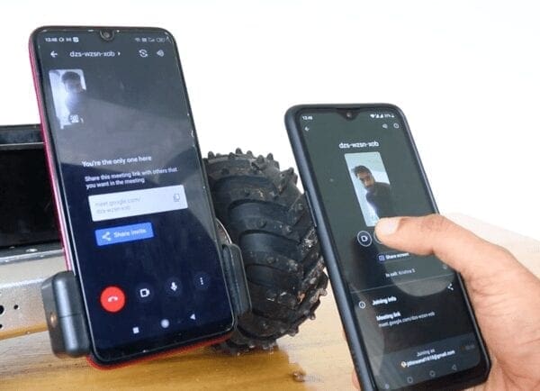
Then, I started a Google meeting on the phone attached to the Telepresence Robot and joined the same meeting from the other mobile phone using another account. Basically, the work was done. I was able to control the robot from My mobile phone, and I could communicate with everyone in front of the robot using voice and video feeds.

I Dont Wanna Go Far
That was a really fun project. But there are limitations. Both these mobile phones must be connected to the same wifi network. So, if I am going to nearby houses and shops, it won’t be a problem. But if we are going far, the network will get disconnected.
A Little Remote Shopping Upgrade?
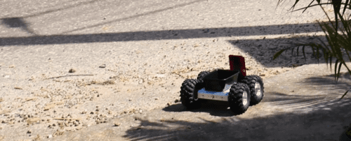
To overcome that, we can use online cloud services so that we can maintain a connection to the DIY Telepresence robot even without a WiFi connection using only mobile data. I used Arduino IOT cloud to do that. Even though there was a delay, it worked flawlessly. I was able to drive the robot a very long distance. If you are interested, do let me know in the comments, it will upload another video for the full tutorial.

Do let me know in the comments if this type of robot can be made practical. If not, do let us know your suggestions on how we can make it practical.
If you ask me, within our compound, nearby houses, and shops, office complex, yes we can make it practical. But if we are sending it out on streets over a long distance in a place like ours, there is a high chance that we will lose the mobile phone or even the whole robot. What is your opinion?