Arduino Plant Watering System | Home Automation Project
A few days back we published an article “Home Automation using Arduino Nano” in our blog which was well-received among hobbyists. We also did a Home Automation System using NodeMCU. In this post, we are going to make our home SMARTER. We will be using the IoT features of Arduino Nano 33 IoT to water the plants using our mobile phone. Yup! Arduino Plant Watering System Sounds cool, right? So, without further ado, let’s get started.
How to make an Arduino Plant Watering System Video Tutorial
For those who are too lazy to read, (including myself) we are linking this video to this page. Hook up your headphone and watch this video, in this video, we explain everything about this project with a demo.

Guys if you like this video and want to see more videos like this, make sure you check out Arduino Project Tutorial Videos. Hit the like button and subscribe to our channel by clicking the subscribe button here. Share your thoughts in the comment box and guys see you in the next video.
Time needed: 1 hour and 30 minutes.
How to setup an Arduino Plant Watering System?
- Gather the components
- Setup the Circuit
- Download and Install Arduino IDE
- Setup the Library and Board
- Modify the below code
- Upload the code
- Test
Now lets take a look at everything in detail
Arduino Plant Watering System – Components Required
- Arduino Nano 33 IoT
- SSR
- An Android Phone with RootSaid – WiFi Command Center installed
- A WiFi network
Lets get familiarised with components
Arduino Plant Watering System Step by Step Instructions
Step 1 – Designing the Circuit
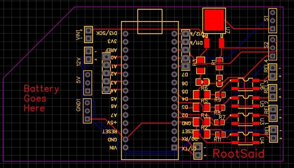
Guys, for our plant watering system, I have designed a PCB layout where you can easily mount your Arduino Nano 33 IOT and your SSR, set this up without using messy wires and cables hanging around. The board is lightweight and can be powered using a 9V battery or a 9-12 V power adapter.

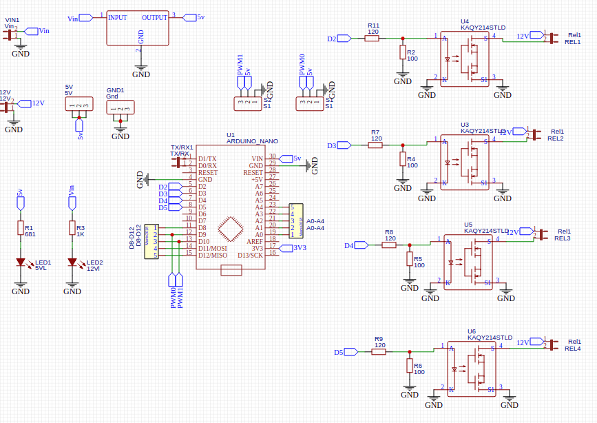
Here, there are 2 voltage inputs – One to power the Arduino and other components on the board and another which will drive the electronic devices connected to the relay, which can depend on the devices.

Here I will be connecting LED strips that work on 12 V So, I will be connecting a 12 V DC adapter. The input power is connected to a 7805 regulator. 7805 is a 5V regulator which will convert an input voltage of 7- 32V to a steady 5V DC supply. There are indicator LEDs across various points for easy troubleshooting.
Soldering
Once you get all the components, it’s time for you to solder them together. Solder all the components onto the board and make sure to check the polarity of the components.
I personally find soldering on this kind of PCBs a fun task, because of this pads soldering becomes very easy. The solder takes up the conical shape and get soldered from all the sides evenly. After soldering the PCB looks like this.
Step 2 – Download, Install and Setup Arduino IDE
This little board can be easily programmed using the world’s most user-friendly Open Source Platform – Arduino. This will be explained in detail below. So, to get started with our Home Automation system using Arduino, the first thing to do is download and install Arduino IDE from Here.
Step 3 – Code for Arduino Plant Watering System
Now we will start coding!
#include <SPI.h>
#include <WiFiNINA.h>
#include <WiFiUdp.h>

int status = WL_IDLE_STATUS;
#include "arduino_secrets.h"
char ssid[] = SECRET_SSID;
char pass[] = SECRET_PASS;
int keyIndex = 0;
unsigned int localPort = 5005;

char packetBuffer[256];
char  ReplyBuffer[] = "acknowledged";

WiFiUDP Udp;

void setup() {
    pinMode(3, OUTPUT);
    pinMode(4, OUTPUT);
    pinMode(5, OUTPUT);
    pinMode(6, OUTPUT);
  Serial.begin(9600);
  while (!Serial) {
    ;
  }

  // check for the WiFi module:
  if (WiFi.status() == WL_NO_MODULE) {
    Serial.println("Communication with WiFi module failed!");
    // don't continue
    while (true);
  }

  String fv = WiFi.firmwareVersion();
  if (fv < WIFI_FIRMWARE_LATEST_VERSION) {
    Serial.println("Please upgrade the firmware");
  }

  // attempt to connect to Wifi network:
  while (status != WL_CONNECTED) {
    Serial.print("Attempting to connect to SSID: ");
    Serial.println(ssid);
    status = WiFi.begin(ssid, pass);

    delay(10000);
  }
  Serial.println("Connected to wifi");
  printWifiStatus();

  Serial.println("\nStarting connection to server...");
  Udp.begin(localPort);
}

void loop() {

  int packetSize = Udp.parsePacket();
  if (packetSize) {
    //Serial.print("Received packet of size ");
    //Serial.println(packetSize);
    //Serial.print("From ");
    IPAddress remoteIp = Udp.remoteIP();
   // Serial.print(remoteIp);
   // Serial.print(", port ");
   // Serial.println(Udp.remotePort());

    int len = Udp.read(packetBuffer, 255);
    if (len > 0) {
      packetBuffer[len] = 0;
    }
    Serial.print("Command Received: ");
    Serial.println(packetBuffer);


 if(strcmp(packetBuffer, "device1on") == 0)
    {
       digitalWrite(3, HIGH);
       Serial.println("Turning Device 1 ON");

    }
 else if(strcmp(packetBuffer, "device1off") == 0)
    {
       digitalWrite(3, LOW);
       Serial.println("Turning Device 1 OFF");
    }
 else if(strcmp(packetBuffer, "device12on") == 0)
    {
       digitalWrite(4, HIGH);
       Serial.println("Turning Device 2 ON");
    }
 else if(strcmp(packetBuffer, "device2off") == 0)
    {
       digitalWrite(4, LOW);
       Serial.println("Turning Device 2 OFF");
    }
else if(strcmp(packetBuffer, "device3on") == 0)    {
       digitalWrite(5, HIGH);
       Serial.println("Turning Device 3 ON");
    }
else if(strcmp(packetBuffer, "device3off") == 0)    {
       digitalWrite(5, LOW);
       Serial.println("Turning Device 3 OFF");
    }
else if(strcmp(packetBuffer, "device4on") == 0)    {
       digitalWrite(6, HIGH);
       Serial.println("Turning Device 4 ON");
    }
else if(strcmp(packetBuffer, "device4off") == 0)    {
       digitalWrite(7, LOW);
       Serial.println("Turning Device 4 OFF");
    }

Serial.println("");
    Udp.beginPacket(Udp.remoteIP(), Udp.remotePort());
    Udp.write(ReplyBuffer);
    Udp.endPacket();
  }
}

void printWifiStatus() {
  // print the SSID of the network you're attached to:
  Serial.print("SSID: ");
  Serial.println(WiFi.SSID());

  // print your board's IP address:
  IPAddress ip = WiFi.localIP();
  Serial.print("IP Address: ");
  Serial.println(ip);

  // print the received signal strength:
  long rssi = WiFi.RSSI();
  Serial.print("signal strength (RSSI):");
  Serial.print(rssi);
  Serial.println(" dBm");
}
Arduino Plant Watering System Code Explained
char ssid[] = SECRET_SSID;
char pass[] = SECRET_PASS;
This is where you enter the ESSID and Passphrase of your network. Before uploading, make sure that you change values to SSID and Passphrase of your WiFi network.
unsigned int localPort = 5005;
This is the port, Arduino will be listening for incoming UDP Packets
pinMode(3, OUTPUT);
pinMode(4, OUTPUT);
pinMode(5, OUTPUT);
pinMode(6, OUTPUT);
The 4 pins we will connecting to the relay input
Serial.print("Attempting to connect to SSID: ");
Serial.println(ssid);
status = WiFi.begin(ssid, pass);
Connect to the WiFi network using predefined ESSID and Passphrase and set up a UDP listener in the predefined port
int packetSize = Udp.parsePacket();
if (packetSize) {
Serial.print("Received packet of size ");
Serial.println(packetSize);
Serial.print("From ");
IPAddress remoteIp = Udp.remoteIP();
 Serial.print(remoteIp);
 Serial.print(", port "); Serial.println(Udp.remotePort());

int len = Udp.read(packetBuffer, 255);
if (len > 0) {
packetBuffer[len] = 0;
}
Serial.print("Command Received: ");
Serial.println(packetBuffer);
Save the UDP packet contents to the variable ‘packetBuffer’ and print its value
if(strcmp(packetBuffer, "device1on") == 0)
{
digitalWrite(3, HIGH);
Serial.println("Turning Device 1 ON");
}
else if(strcmp(packetBuffer, "device1off") == 0)
{
digitalWrite(3, LOW);
Serial.println("Turning Device 1 OFF");
}
else if(strcmp(packetBuffer, "device12on") == 0)
{
digitalWrite(4, HIGH);
Serial.println("Turning Device 2 ON");
}
else if(strcmp(packetBuffer, "device2off") == 0)
{
digitalWrite(4, LOW);
Serial.println("Turning Device 2 OFF");
}
else if(strcmp(packetBuffer, "device3on") == 0) {
digitalWrite(5, HIGH);
Serial.println("Turning Device 3 ON");
}
else if(strcmp(packetBuffer, "device3off") == 0) {
digitalWrite(5, LOW);
Serial.println("Turning Device 3 OFF");
}
else if(strcmp(packetBuffer, "device4on") == 0) {
digitalWrite(6, HIGH);
Serial.println("Turning Device 4 ON");
}
else if(strcmp(packetBuffer, "device4off") == 0) {
digitalWrite(7, LOW);
Serial.println("Turning Device 4 OFF");
}
Turns the output of the pins to HIGH or LOW depending upon the packets received.
Step 4 – Install RootSaid WiFi Command Center from Google PlayStore
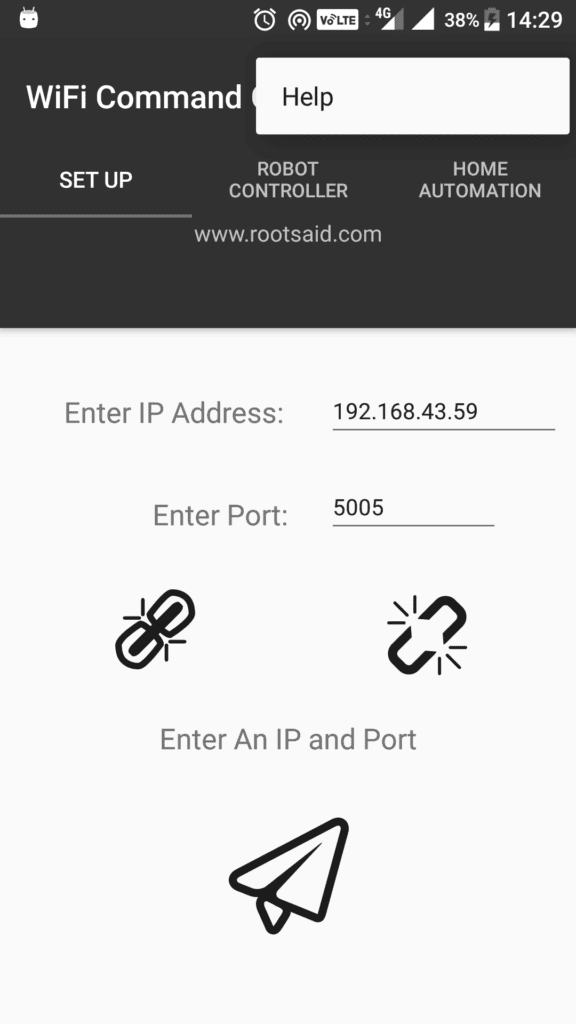
RootSaid WiFi Command Center is a simple lightweight android application that can be used to control robots and Raspberry Pi and Arduino Home Automation over WiFi. All you have to do is connect your mobile phone to the network, enter the IP address and port of the server (the Arduino of our Home Automation system using Arduino) and control it using the On-Off buttons. Click here to know more about this App.

Click Here to Download this app from Playstore.
Step 5 – Tesing Arduino Plant Watering System
Now all you have to do is start the App, enter the IP address of the Pi and port it is listening to (5005).
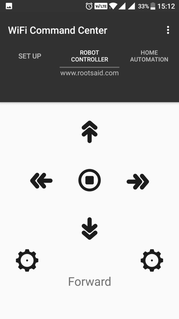
Load the IP and Port using the link button and navigate to the Home Automation Tab.
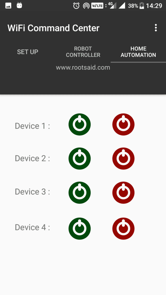
That’s it, your Home Automation system using Arduino is now ready. You can now control devices connected to your Arduino using this simple app and turn it on and off.