
Arduino POV Display Tutorial | POV LED Strip Tutorial
Introduction
Hey guys, welcome back. In this post, I will show you how you can make an LED POV Display using Arduino and Wemos D1 Mini. Here I will show you how to design the circuit, how to make the PCB and how to assemble and set up your very own Arduino LED POV Display.

Components Needed
- Wemos D1 Mini
- Arduino POV Display PCB
- Battery
- 1000 RPM DC Motor
- LEDs
- Resistors
What is POV?
In simple terms, persistence of vision is our eye’s property of keep seeing (or illusion of seeing) an image of something, for a fraction of a second even after the object has moved out of sight. This is because the image of the object that was once visible stays in your retina even after the object is no longer visible to the eye. In other words, the image “Persists” in your sight for a short amount of time even after it has moved out of sight.
How Arduino LED POV Display Works?
In this project, we make use of this principle to get an illusion of seeing actual letters by spinning an array of LEDs that are glowing in a specific pattern.[AdSense-C]
We turn ON LEDs and turn OFF LEDs in such a way that the different glowing images overlap each other forming alphabets.
Arduino LED POV Display Circuit


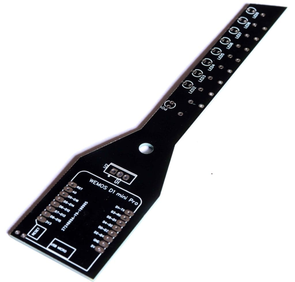
Designing the PCB
To make everything more compact I have designed my own PCB. Just yesterday I got it in my hand. And this is it.

Drawing Schematics using EasyEDA
To draw circuits and design PCBs, we have online PCB designing tools from EasyEDA, provides all the necessary capability for online PCB Design and PCB Printing of Circuit Boards with hundreds of components and multiple layers with thousands of tracks.
I drew a circuit in EasyEDA which included all the components on the breadboard – the Resistors, LED and Wemos D1 Mini.
I also added a 7805, regulator which will helped me to provide an input voltage between 7 volt and 35 volt in the input, so that I can use a 5 volt USB power supply, 9-volt battery or even a 12 volt lithium polymer battery without any issues.
I also added an indicator LED that will let me know if something stopped working. You will find the circuit to my EasyEDA below.
Connections
Arduino (Wemos D1 Mini) – LED#
- Led 1 – Pin 2
- Led 2 – Pin 3
- Led 3 – Pin 4
- Led 4 – Pin 8
- Led 5 – Pin 9
- Led 6 – Pin 5
- Led 7 – Pin 6
- Led 8 – Pin 7 (Not Used for Now)
Next, designing the PCB. PCB Layout is actually a significant part of PCB Design, we use PCB Layouts to make PCBs from schematics. I designed a PCB where I could solder all the components together.[AdSense-C]
For that, first save the schematics and from the top tool list, Click on the convert button and Select “Convert to PCB”. This will open up a window like this. Here, you can place the components inside the boundary and arrange them the way you want. The easy way route all the component is “auto-route” process. For that, Click on the “Route” Tool and Select “Auto Router”.
This will open up an Auto Router Config Page where you can provide details such as clearance, track width, layer information etc. Once you have done that, click on “Run”.
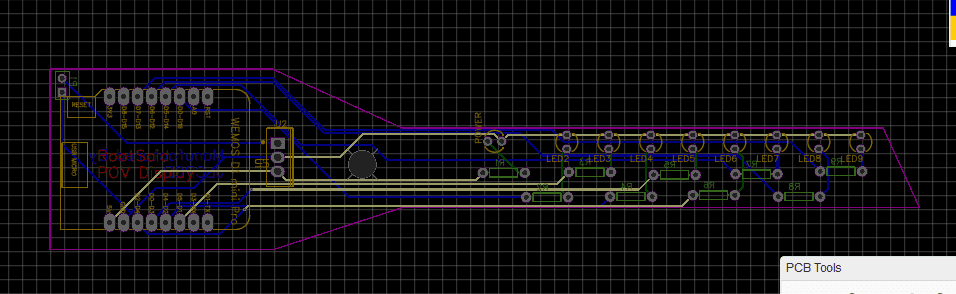

Thats it guys, your layout is now complete. This a 4 layer PCB which means the routing is there in 4 Layers of the PCB. You can now download the Gerber file and use it to manufacture your PCB from JLCPCB.
Getting the PCB Manufactured from JLCPCB
JLCPCB is a PCB manufacturing company with a full production cycle. Which means they start from “A” and finishes with “Z” of PCB manufacturing process. From raw materials to finished products, everything is done right under the roof.


Go to JLC PCBs website and create a free account. Once you have successfully created an account, Click on “Quote Now” and upload your Gerber File.
Gerber File contains information about your PCB such as PCB layout information, Layer information, spacing information, tracks to name a few.
Below the PCB preview, you will see so many options such as PCB Quantity, Texture, Thickness, Color etc. Choose all that are necessary for you.

Once everything is done, click on “Save To Cart”. In the next page, you can choose a shipping and payment option and Check Out Securely. You can either use Paypal or Credit/Debit Card to pay.
PCB is Done. The PCB will be manufactured and shipped with in days and will be delivered to your doorstep within the mentioned time period.
Soldering and Assembling
Once you get the PCB, its time for you to solder all the components. Place all the components in their respective places and solder them up. This wont take more that 10 minutes. Before soldering Wemos D1 Mini, it is always better to solder female header pins to the PCB and then placing Wemos D1 Mini on top of it. This way, if the brain stop working, you can always replace it with a new one without desoldering.

Coding Arduino LED POV Display
Our work is almost done. Now you can upload the below code to Arduino.

Get Arduino POV Display Code[AdSense-A]
Here, the code is to Display “RootSaid”. You can change it anything you want. Sp() is function to display blank space.
Once the code is uploaded, you will see the light starts to blink. Dont worry it doesnt make any sense. It will make sense only when it starts rotating.
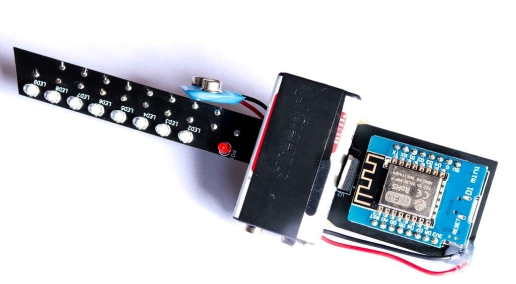
Connecting Battery and DC Motor to Arduino LED POV Display
Now you can fix a 9V battery to the PCB.
Here I have used a 12 V DC motor to rotate the LED Strip PCB. You can attach the shaft of the motor to the PCB the way you like.

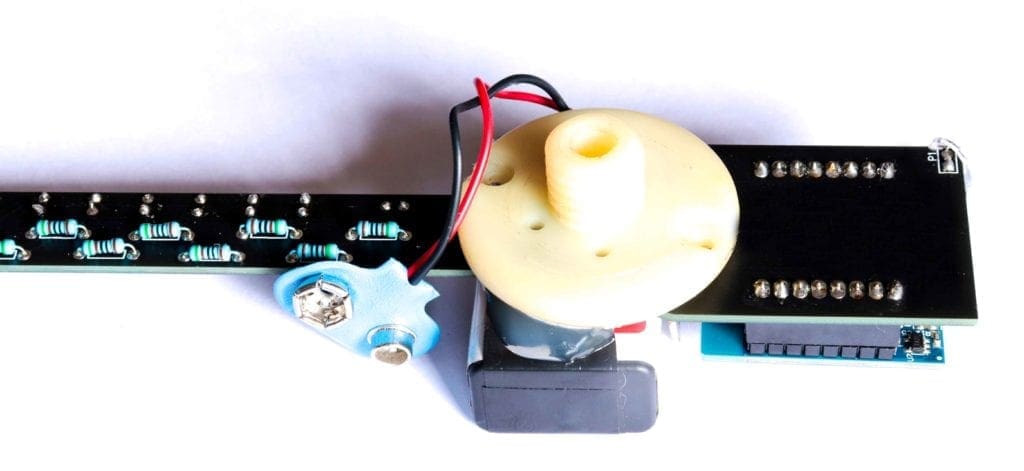
What I did was, I took out a dummy wheel shaft, removed the shaft and connected the flat circular portion to the PCB using hot glue gun and connected the shaft of our motor directly to it. Make sure you
Make sure you are connecting the motor at a point where the wight balances of equally.
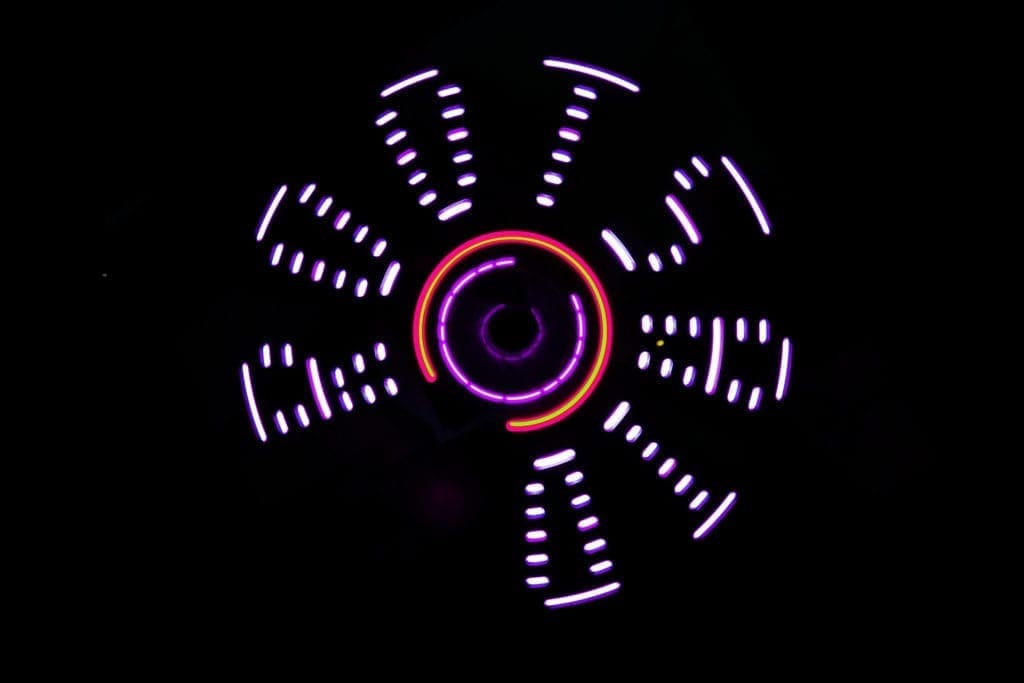
Arduino LED POV Display First Run
Now you can connect the 9V battery to you PCB. You will see the light starts to blink. Connect the battery to the motor so that it starts to spin. As the motor reaches top speed, you will see amazing characters being displayed.

Here I have used a 1000 RPM. One thing you can do here is, you can control the speed of the DC motor using a speed regulator or a motor driver IC using PWM. This will help you regulate the speed if the motor RPM is high.
Why did I choose Wemos D1 Mini? The reason I chose it is, it is a cheap board that has WiFi capability. This is the first part of my project. In the next part I will show you how you can control the speed of the motor and display custom messages sent from mobile phone or laptop via WiFi without reprogramming.


This is awesome. I love this project. Never thought POV Display using Arduino is this simple.
Amazing Tutorial. Keep it up.