Home Automation using Arduino and Alexa | Arduino Alexa Projects
In this post, I will show you how you can set up a Home Automation using Arduino and Alexa. I will be giving you complete instructions including the circuit diagram, PCB files if you want to make a PCB, and the codes. I will provide the link to everything in the description so that you can redesign the entire thing, customize it and then make your own version of it.
Home Automation using Arduino and Alexa Video Tutorial
In this video, I will show you how you can set up an Alexa-based Smart Home using Arduino. I will be giving you complete instructions including the circuit diagram, PCB files if you want to make a PCB, and the codes. I will provide the link to everything in the description so that you can redesign the entire thing, customize it and then make your own version of it.
![How to make Voice Control Home Automation System using Arduino? [Easier than you Think]](https://i.ytimg.com/vi/zdHL3NZMMQ4/hqdefault.jpg)
Components Needed to make a Home Automation using Arduino and Alexa
The following are the components that is needed to build your Alexa Home Automation System using Arduino
- Arduino Nano 33 IoT (or any WiFi-enabled Board)
- SSR
- An Android Phone with Alexa App installed
- A WiFi network
To set one up, the first thing you need is to select an Arduino board. For this project, I’ll be using this Arduino Nano 33 IoT. This enables us to control the devices using Alexa in your mobile phone as well as from echo dot. The Arduino Nano 33 IoT is the best Arduino board available if you want to add network connectivity to your project. This is an IoT board, light, and compact and it’s the same size as that of nano. Yes, you can use any board with network connectivity for this project.
Drawing Schematics and PCB Design using Altium

I use Altium Designer to draw the circuit and design the PCB. It is a powerful tool that can be used to design and create your own PCBs for your project as well as complex and multiplayer PCBs for industrial use. Here is the link to the Altium trial version.
Home Automation using Arduino and Alexa Circuit and PCB Layout
First, take a look at the circuit diagram.

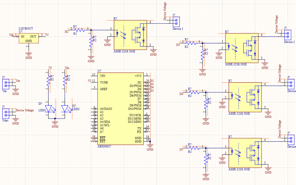
Here we are in Altium designer. Here I will be connecting LED strips that work on 12 V So, I will be connecting a 12 V DC adapter. The input power is connected to a 7805 regulator. 7805 is a 5V regulator which will convert an input voltage of 7- 32V to a steady 5V DC supply. There are indicator LEDs across various points for easy troubleshooting.
Here, there are 2 voltage inputs – One to power the Arduino and other components on the board and another which will drive the electronic devices connected to the relay, which will depend on the devices.
Four GPIO pins of Arduino are connected to SSR or Solid State Relays which is a type of Relay. Relays are switching circuits that can close and break circuits mechanically. That means it can control an electrical circuit by closing and breaking connections in that circuit.
A solid-state relay (SSR) is similar to a type of Relay. SSR is basically an electronic switch that switches on & off when a small external voltage is applied across its control terminals. We will be using these relays in our Arduino Smart Home.

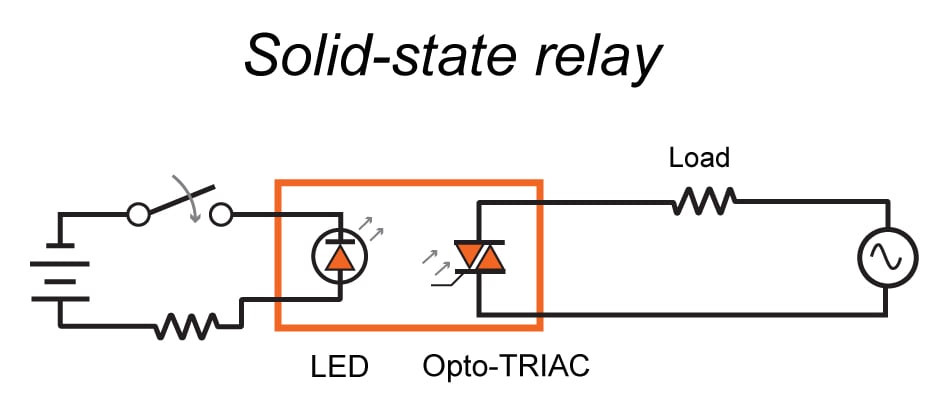
Of course, you can use an electromechanical relay for this project. If you are using ordinary electromechanical relay, It is better to use a simple relay driver circuit to turn on the relay instead of connecting Arduino Output directly to Relay input.
This is just my design, Like I said earlier, I will provide the schematics in the description so that you can redesign the entire thing, customize it and then make your own version of it. Or you can make my version as such. Whatever you do, first thing is to try it out on a breadboard. Once you are getting the output, then you can use it as such or make your PCB.

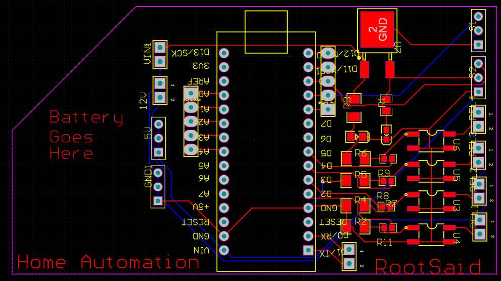
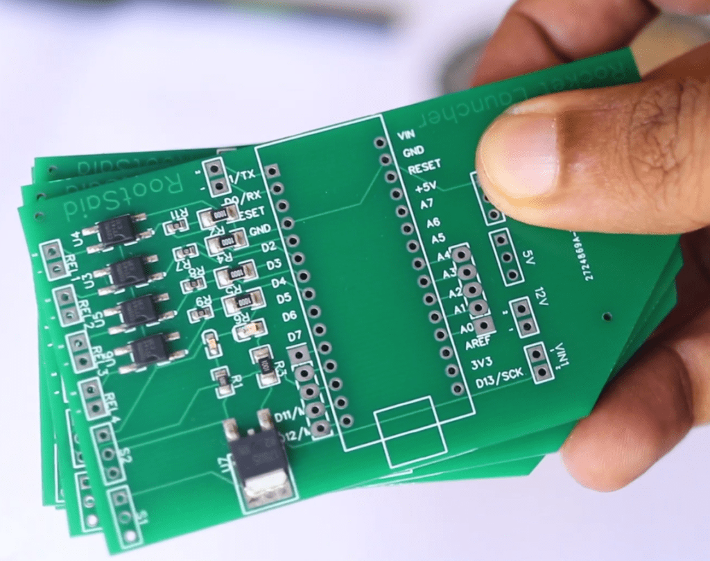
I decided to go with the PCB. I have designed a PCB layout where you can easily mount your Arduino Nano 33 IOT and your SSR, set this up without using messy wires and cables hanging around. And it’s cool to make your own PCBs for your project right? The board is lightweight and can be powered using a 9V battery or a 9-12 V power adapter.
Ordering the PCB
I ordered by PCB from PCBWay. PCBWay is a PCB manufacturer specializing in PCB prototyping, low-volume production, and neat and tidy PCB Assembly. To order your PCB from the PCB way, Go to the PCBWay website and fill in the basic board details in the instant order form.

From there you will be directed to a form where you can provide more elaborate board details. Update your board information in the PCB Specification screen. In the next screen, you should be able to upload your Gerber file and submit it for review. Once the review is completed, all that is left is to add to the cart, make the payment, and wait for your PCBs to arrive.

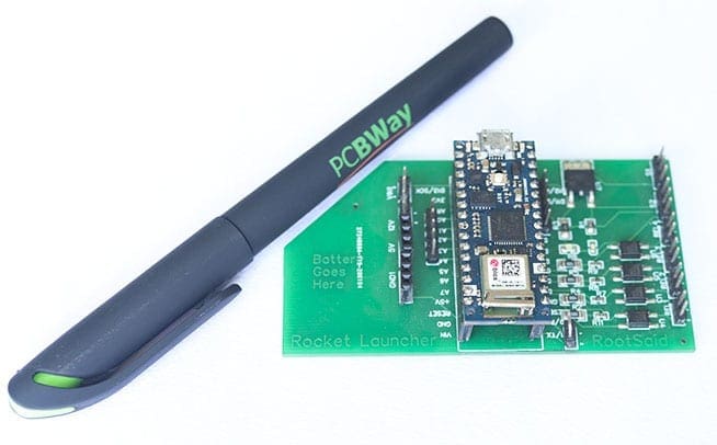
Once you get all the components and the PCB, it’s time for you to solder them together. Solder all the components onto the board and make sure to check the polarity of the components. After soldering the PCB looks like this.

Arduino IoT Cloud
Now, let’s get down to the software part. Here, I will be programming the board using Arduino IoT Cloud. o to things and click on ‘create thing’. This is the page where you will be able to see complete details about your project. Here you will see complete details about your project like the board attached, variables, network, sketch, etc. First, we will give our project a name.

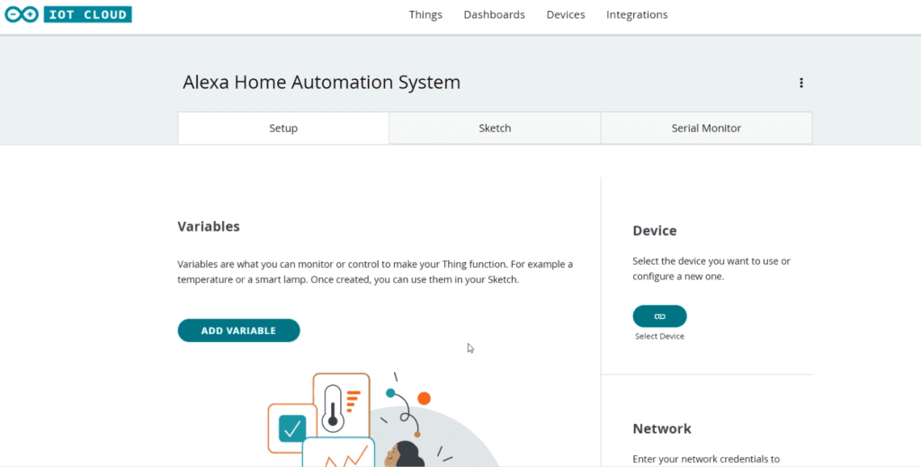
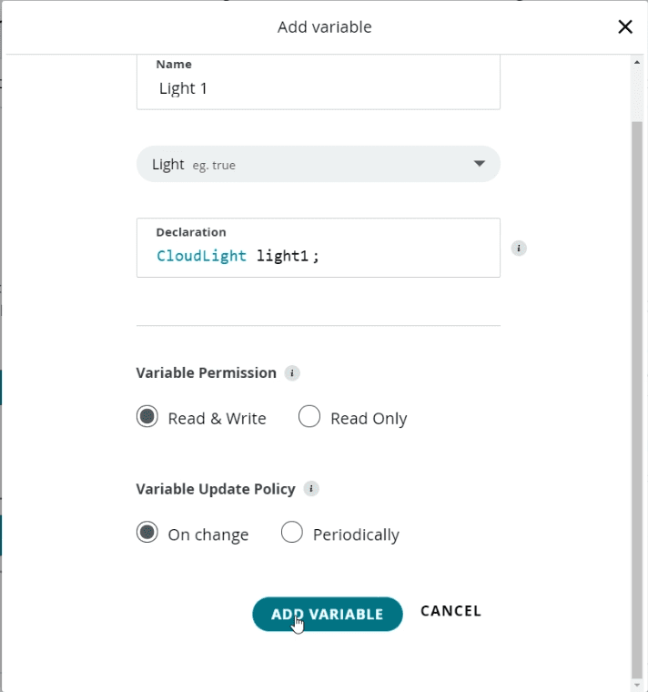
Next, we will attach this project to the board Arduino Nano 33 IoT. After that, we will add 4 boolean variables to control the devices. Lets name it Light 1 – 4. Make sure the variable type you select is alexa compatible.

Now, we will configure the network connection. For that, you can use the configure button under the network. Here, you should provide the WiFi name and password. Now its time to code!
Coding the Alexa Home Automation System
The advantage of using Arduino IoT cloud is once you have set up your thing and all the variables it will automatically generate a skeleton code which will include all the variables and critical function which is required to run the code. We just have to add extra variables and functions.
Now I will be removing all unnecessary comments so that it will look, neet. And here is our final code guys now let’s take a deeper look into it.
In the setup function, we will initialize the serial communication, communication with Arduino cloud, set the pin mode, and then prepare the carrier to run the remaining code. .
These are the four functions that will run when there is any change in the corresponding variables. When one of the values changes, the corresponding function will run. For example, when the light1 variable changes, the onlight1Change function will run. If the value of light 1 is 1, it will turn on light 1, else it will turn off light 1. The same goes with light 2, light 3, and light 4. That was really simple, right?
Now, how do we change the variable? That’s right, we will toggle the switch using Alexa. Your code is finished and you can upload your code to your board.
Arduino Skill for Alexa
Now, take out your smartphone and launch Alexa App. Go ahead and install the Arduino Skill for Alexa and login with your credentials.


Now tap on discover devices. It will start scanning for any IoT-based Alexa-supported devices. Once the scan is completed, it will show you all the variables we created earlier. Setup those devices and click done. That’s it, guys.
Home Automation using Arduino and Alexa

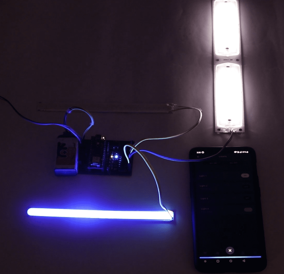
Now, you should now be able to control the devices using your voice command via Alexa. You can use Alexa in your mobile phone app as well as Amazon devices like Echo dot to talk to Alexa and control these devices.
If you like this project and really interested in building amazing DIY projects make sure you subscribe to our channel by hitting the subscribe button here. Now, let’s get started with the project.