
How to make an Arduino Board in your Home? DIY Arduino UNO
In this video, we are going to be making our own customized Arduino Uno board and I will be showing you how easy it is to make one. I will be explaining everything in detail, in very simple terms so that it will be very easy for you to understand. Everything you need to build your Arduino board is in the description. Make sure you check it out! Let’s get started.
How to make an Arduino Board – Video Tutorial?
Too lazy to read? we have a complete video tutorial for you! Push the play button below, sit back and enjoy!
![How to make an Arduino Board at your Home [Complete Step by Step Instructions] - DIY Arduino UNO](https://i.ytimg.com/vi/0B_wGtMP_eA/hqdefault.jpg)
Components needed to make Arduino Board
- ATMega328
- 16 MHz Crystal Oscillator
- Capacitors
- Resistors
- LED
- Header pins
- FTDI Programmer
- Connecting Cables
DIY Arduino UNO – Circuit
Bare minimum configuration
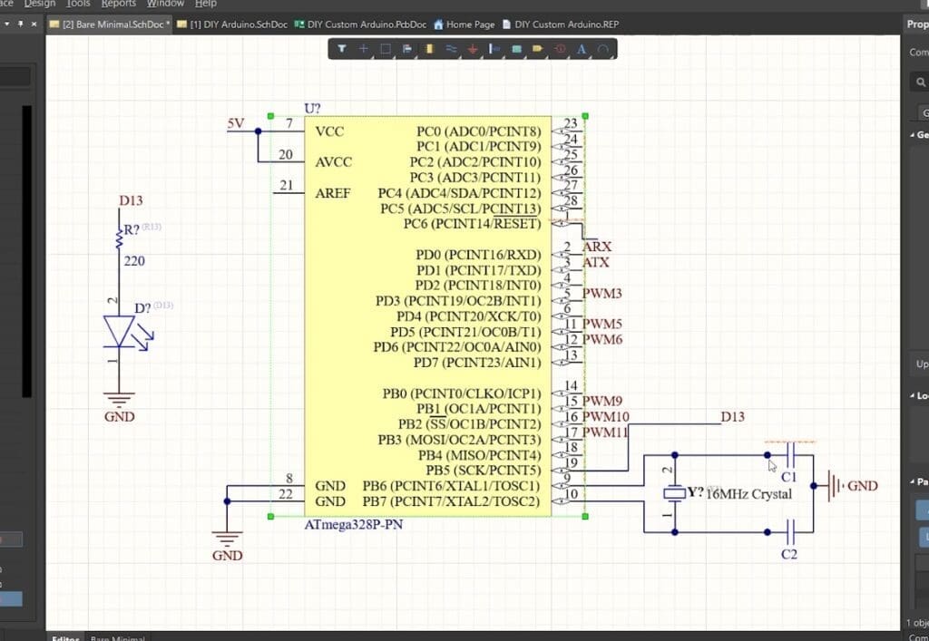
In order to make our Arduino board, we will need a microcontroller, which will be the one doing all the mathematical calculations and doing all the logical decisions. So which microcontroller do we use in our Arduino Board? Here, will be using an ATMega328. The microcontroller can’t operate without the bare essentials. In order to function, it just needs a minimal amount of setup. Let’s look at the bare minimum configuration.

I used an Altium designer to draw the circuit and design the PCB. It is a powerful tool that can be used to design and create your own PCBs for your project as well as complex and multiplayer PCBs for industrial use. I will leave the link to the free trial version in the description. I have been using it for the past 3 years. If you are an electronic engineer, it’s gonna be really useful for you. Also, if you are a student, you will get 6 months license completely free of charge! So do make use of it!
To get started with the bare minimum configuration, we will need the ATMega328 chip, 16 MHz crystal oscillator, and two capacitors. Crystal Oscillator will be connected between pins 9 and 10 and the two ends are connected to the ground. Why do we need a crystal oscillator? Every microcontroller needs a clock signal and every action inside the chip is based on the clock. For the Arduino, clock signals are provided by a Crystal oscillator.
Once you power up the ATMega328, it will work. But that is not enough, is it? We will be making it more stable, versatile, and more USEFUL. Let’s make it closer to the real Arduino Board.
Making a Custom Arduino Board
This is the point where we will be connecting the input voltage. Input power will be connected to a 7805 voltage regulator which will convert a voltage between 7-32 volt to a steady 5V DC Supply, which will be fed to Arduino and other components.

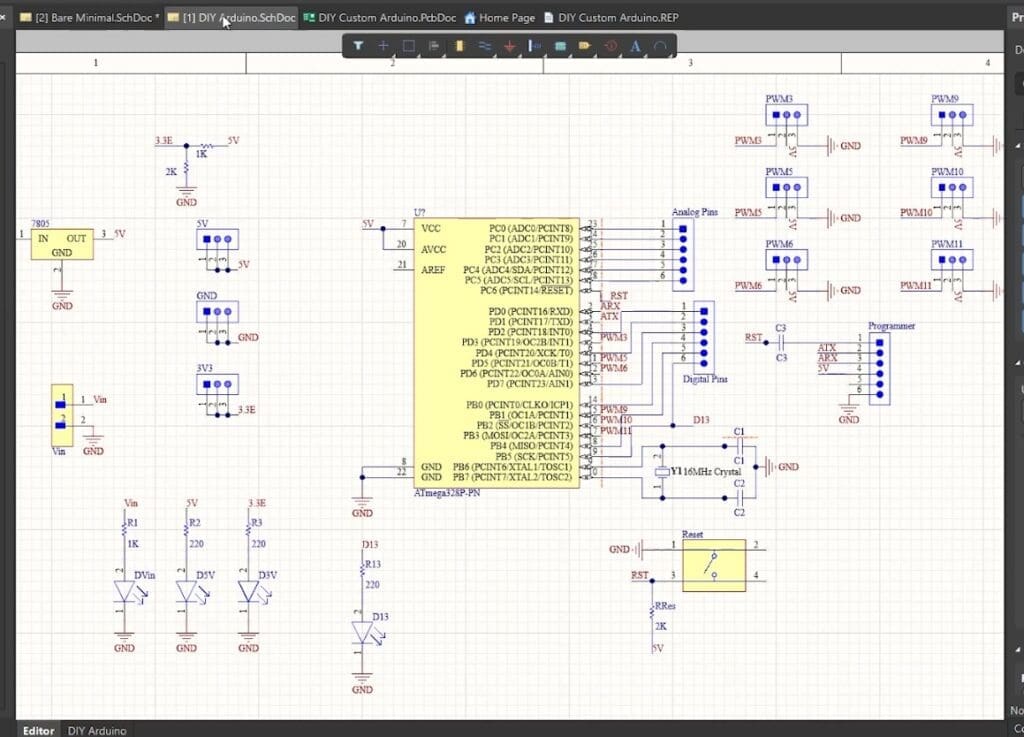
This 5V is also fed to a voltage divider circuit which will reduce the voltage to a 3.3V DC voltage. This will be really helpful when we are connecting modern sensors and modules as most of them work on 3.3V.
PWM pins are connected to these 3 pin headers, where the first pin is connected to corresponding PWM pins, the second pin is connected to 5V and the third pin is connected to GND. This is the pin configuration of most of the servo motors and sensor modules; which means, you can connect your Servo motor directly to this Arduino Board.
Then here are the Analog pin headers, which are connected to the Analog Pins, and here are the digital pin headers that are connected to the remaining digital pins.
And we have some indicator LEDs that will help us to troubleshoot if anything goes wrong. This LED is connected to Pin 13 of the ATMega328.
Now the real question is how do we program this Arduino Board? The ATMega328P chip can’t communicate with USB directly. Their way of communication is UART.

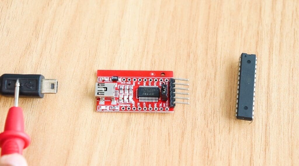
So in order to program the Atmega328 using USB, UART data from the chip is sent to another module that can convert UART to USB and vice versa, which will bridge the two technologies together. In our case, we will be using an FTDI module that will handle the communication between ATMega328 and our computer. This is where we will be connecting the FTDI module. The Tx pin of the FTDI module is connected to the Rx pin of ATMega328 and the Rx pin of the FTDI module is connected to the Tx pin of ATmega328.
Designing the PCB Layout
Once the circuit was finished, I started working on the PCB Layout. Using Altium designer, creating a PCB layout is really easy. We can simply arrange all the components inside the board, route the tracks and create a board layout and all these can be done within 10 minutes.

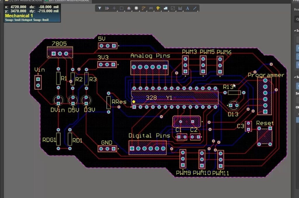
This Arduino board is designed in such a way that it will be easy for you to connect your sensors and servo motors directly to the board. These are pins where you will be connecting the servo motors if you want.
As you can see here, routing is here on both sides of the board which means, this is a dual-layer PCB. Once everything is designed, all you have to do is export the Gerber file.
Getting PCBs Done
I ordered PCB from PCBWay. PCBWay is a PCB manufacturer specializing in PCB prototyping, low-volume production, and neat and tidy PCB assembly and you can create a variety of PCBs with different specifications. If you are interested in making your own PCBs for your project, check out the link below. We will look into it in a second. You can get a 5 dollar discount when you sign up using the below link and get an additional 5 dollar discount at the checkout by providing the coupon code PCBWayLab.


To order your PCB from PCBWay, go to the PCBWay website and fill in the basic board details in the instant order form. From there you will be directed to a form where you can provide more elaborate board details. Update your board information in the PCB specification screen.
Now update the board information in the PCB specification screen. I want to give the black color to these PCBs, so I chose the black color for the solder mask.
In PCBWay, we can select a variety of colors for the PCBs such as purple, black, orange, and even create transparent PCBs by selecting a transparent solder mask.

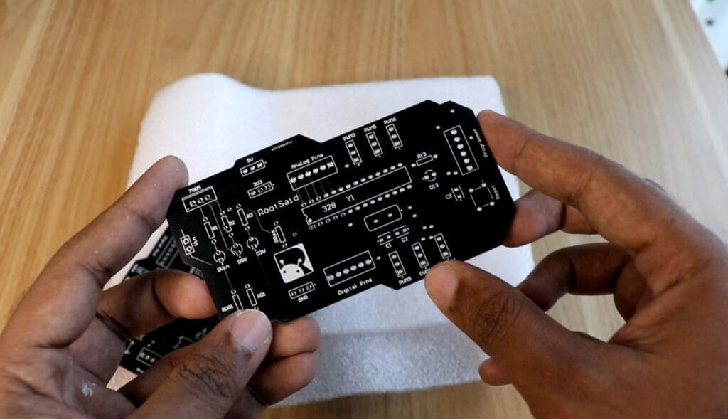
Also, I chose a white silkscreen instead of black. Perfect. On the next screen, we should be able to upload the Gerber file and submit it for review. Once the review is completed, all that is left is to add to the cart, make payment, and wait for the PCBs to arrive.
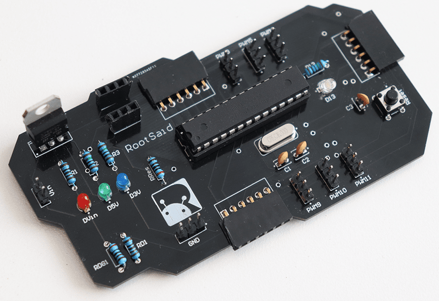
Once the PCB arrives and you got all the components, start soldering. While soldering, make sure you check the polarity of the components and check the positioning of the IC.
Once it is soldered, our Arduino Board looks like this!

Programming
Now it’s time to upload the first code! To do that, connect the Arduino Board to the FTDI module and connect the FTDI module to the computer. Make sure you have installed the correct drivers for the FTDI module on the computer.
No fire up Arduino IDE and open the Blink example sketch. Now select the board – Arduino Uno and select the right port.
Once that is done, click on upload. The code will be compiled and will be uploaded to the board via the FTDI module. This is how we can make our own Arduino board. That was cool, right? Everything you need to build your Arduino board is in the description. Make sure you check it out! If you like this video, do support our channel by giving this video a like and subscribe to our channel to see more videos like this!