Controlling Photoshop with Arduino Nano RP 2040 | Arduino HID Project
What if there was something that we could use to quickly change or swap between the tools in Adobe Photoshop or Premiere Pro with the push of a single button? Or change the brush size by turning a knob? If you have ever thought about that, you are gonna love this video.

My name is Jithin and I am super excited to teach you everything you need to know about home automation, robotics, and other fun DIY projects using Arduino and raspberry pi. If you are a true fan of all these things make sure you check out our channel. You are gonna really love it. If you want more videos like this. Make sure you subscribe to our channel by hitting the subscribe button right here.
What is Photoshop?
You all know what photoshop is right? Photoshop is software used to edit digital images. There are lots of tools in it which you can use to manipulate your image.

One way of quickly swapping between tools is to use keyboard shortcuts. Keyboard shortcuts are key combinations which when pressed in the right order, will enable a particular tool or change the properties of a particular tool, for example changing the brush size.
What is HID?
This is an Arduino Nano RP 2040. This Arduino Board can act as HID (Human Interface Device), as a keyboard or mouse, and send keystrokes through the USB port like a real keyboard.
We will be making use of this functionality to make a controller that will help us to swap between tools as well as change properties, with a push of a single button or turning the knob.
The Circuit
I’ve always been interested in electronics and technology and making my own PCBs for my projects. I used Altium Designer to draw the circuit and design the PCB. It is a powerful tool that can be used to design and create your own PCBs for your project as well as complex and multiplayer PCBs for industrial use.

I will leave the link to the free trial version in the description. Also, if you are planning to buy it, there is an awesome 30% discount by purchasing it using the link below! So do make use of it!
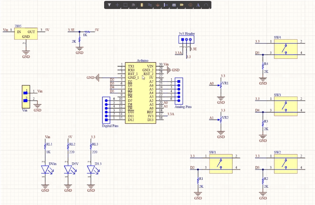
Here we have an Arduino Nano RP 2040 which is the brain of this project. Then we have 4 push buttons connected to 4 digital pins of Arduino – D2, D3, D4, and D5. We will be assigning different key combinations to all these switches while coding.
Then we have two potentiometers right here. The output of these ports is connected to two analog pins A0 and A1. Then we have indicator LEDs at various points. There are two ways to power this board. One is to use an external power source and the other is to use the voltage from the USB port.
If you are powering it through Vin, you can provide a DC voltage between 7 to 32 volt, which will be fed to the 7805 voltage regulator. The output of the 7805 is 5V and this 5V is fed to a voltage divider circuit which will convert it to 3.3V.
You can easily switch between the two voltage sources using this header right here. The reason why we are converting to 3.3V is, the operating voltage of Arduino Nano RP 2040 is 3.3V. Providing a voltage greater than 3.3V will fry the chip.
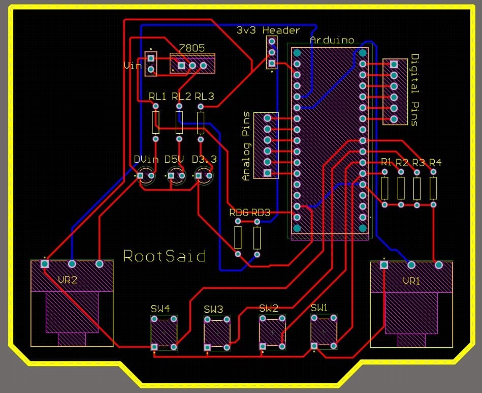
Once the circuit was finished and tested, I designed a compact PCB using Altium, where I can fix all the components neatly. Here you can see routing is on both sides of the board which means it is a dual-layer PCB.

Getting PCB Done
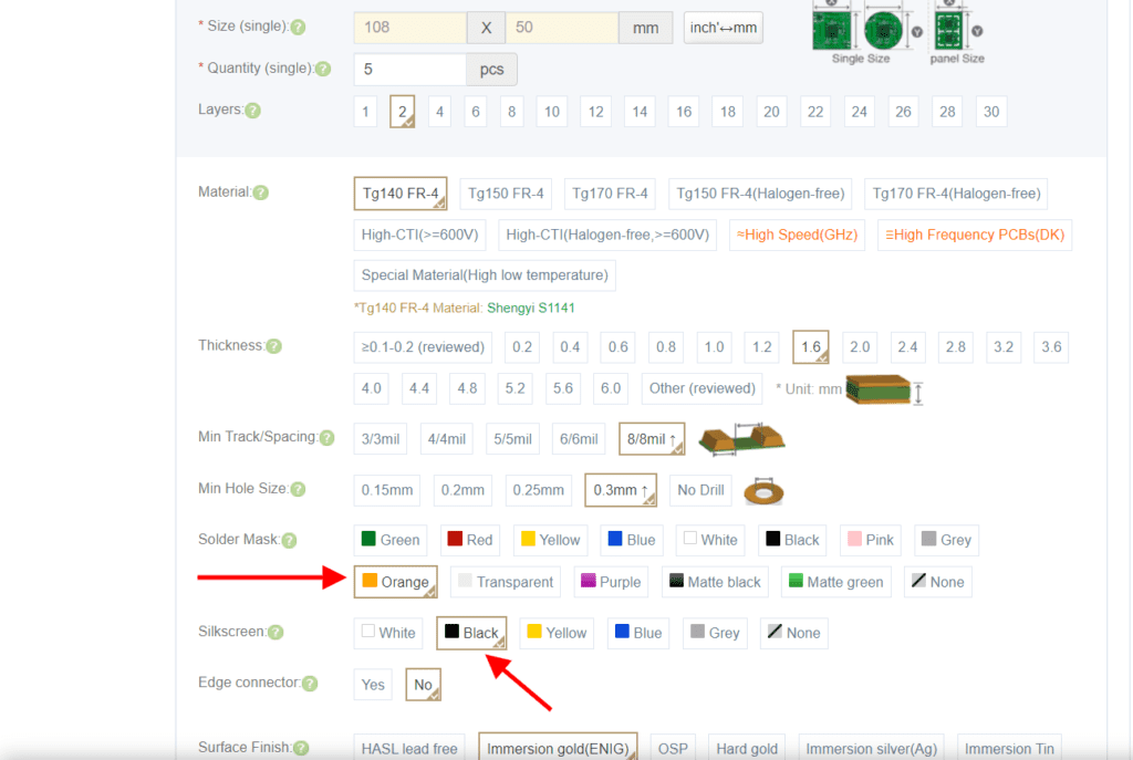
I ordered PCB from PCBWay. PCBWay is a PCB manufacturer specializing in PCB prototyping, low-volume production, and neat and tidy PCB assembly.
To order your PCB from PCBWay, go to the PCBWay website and fill in the basic board details in the instant order form. From there you will be directed to a form where you can provide more elaborate board details. Update your board information in the PCB specification screen. On the next screen, you should be able to upload your Gerber file and submit it for review. Once the review is completed, all that is left is to add to the cart, make payment, and wait for your PCBs to arrive.

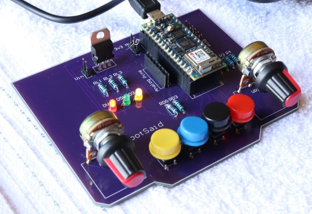
Once you get all the components and the PCB, it’s time for you to solder them together. Solder all the components onto the board and make sure to check the polarity of the components. After soldering the PCB looks like this.

Coding
Now start Arduino IDE and make sure you have installed Arduino Nano RP 2040 board as well as USBHID library. These two libraries are necessary for the Arduino to work as HID.
#include <PluggableUSBHID.h>
#include <USBKeyboard.h>

const int buttonPin1 = 2;
const int buttonPin2 = 3;
const int buttonPin3 = 4;
const int buttonPin4 = 5;
const int ledPin =  13;

USBKeyboard Keyboard;

int button1State = 0;
int button2State = 0;
int button3State = 0;
int button4State = 0;
int pot1 = 0;
int pot2 = 0;

void setup() {

  pinMode(ledPin, OUTPUT);
  pinMode(buttonPin1, INPUT);
  pinMode(buttonPin2, INPUT);
  pinMode(buttonPin3, INPUT);
  pinMode(buttonPin4, INPUT);
  pinMode(A0, INPUT);
  pinMode(A1, INPUT);

  Serial.begin(9600);
}

void loop() {
  button1State = digitalRead(buttonPin1);
  button2State = digitalRead(buttonPin2);
  button3State = digitalRead(buttonPin3);
  button4State = digitalRead(buttonPin4);
  pot1 = analogRead(A0);
  pot2 = analogRead(A1);

if (button1State == HIGH) {
    digitalWrite(ledPin, HIGH);
    Serial.println("Button 1 Pressed");
    Keyboard.key_code('t', KEY_CTRL); //Resize
    delay(500);
  } else {
    digitalWrite(ledPin, LOW);
  }

if (button2State == HIGH) {
    digitalWrite(ledPin, HIGH);
    delay(500);
    Serial.println("Button 2 Pressed");
    Keyboard.key_code('u', KEY_CTRL); //Press CTRL, u
  } else {
    digitalWrite(ledPin, LOW);
  }

if (button3State == HIGH) {
    digitalWrite(ledPin, HIGH);
    delay(500);
    Serial.println("Button 3 Pressed");
    Keyboard.key_code('j', KEY_CTRL); //Press J
  } else {
    digitalWrite(ledPin, LOW);
  }

if (button4State == HIGH) {
    digitalWrite(ledPin, HIGH);
    Keyboard.key_code('v'); //Press V
    delay(500);
    Serial.println("Button 4 Pressed");
  } else {
    digitalWrite(ledPin, LOW);
  }


if ((pot1>=750)&&(pot1<=400))
{
  Serial.println("Pot 1 Min"); // No Change
}
else if (pot1>750)
{
  Keyboard.key_code('-', KEY_CTRL); //Zoom Out
  delay(500);
}
else if (pot1<=400)
{
  Keyboard.key_code('+', KEY_CTRL); //Zoom In
  delay(500);
}

}
First, we will include the necessary header files. Now we will initialize all the variables, assign them to pins where the buttons and ports are connected.
In the setup function, we will set the pin mode and initialize serial communication. In the main function, we will fetch the status of each pin using DigitalRead and AnalogRead and store the value in different variables.
The next part is the action, and it’s entirely up to you. You can customize it the way you want. But I will show you how I configured the action for my PC. Here, I have written if condition for each and every button as well as two potentiometers – like if the button is pressed, send a particular keystroke.
For example, if button1 is pressed, send keystroke ctrl+t, which will resize the currently selected image. If pot1 is turned right, it will zoom in on the canvas, or if turned left, zoom out on the canvas. Similarly, you can assign keyboard shortcuts to the remaining 3 buttons and pots.
This is just a glimpse of what you can do with it. There are many useful things you can do, for example, do one thing when you momentarily press the button, another thing when you press and hold a button, and another thing when you release the button, Like I said Its entirely up to your convenience.

Now simply select the right board and port and upload the code.
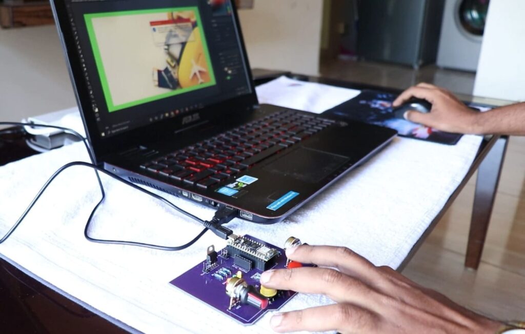
Testing
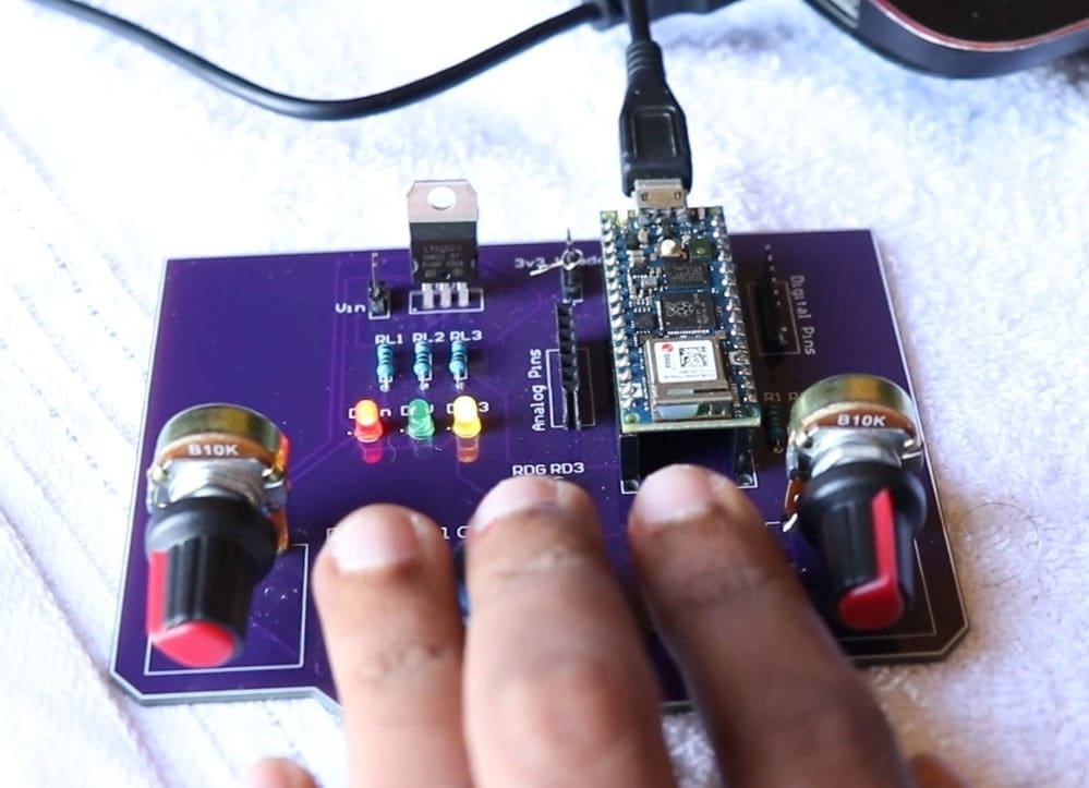
Now all you have to do is connect the Arduino to your PC using USB Cable, fire up Photoshop or Premiere and try pressing the button or moving the potentiometer. Once you get a hang of it, you are never going to let it go.


Ask all your doubts in the comments down below. If you find this video useful, make sure you give this video a thumbs up. Subscribe to this channel for more awesome videos.