Create a High Current Motor Driver Shield for Arduino using Piggybacked L293D Hack!
Hey, guys welcome back, In this post, I will show you how you can make your own high current motor driver shield for Arduino which can be used to drive Robots that uses more than 2 motors. Using this, you can drive up to 4 high current DC motors simultaneously and independently using your Arduino Nano.

It all started when..
Months before we built a 2 wheel drive robot for beginners remember?
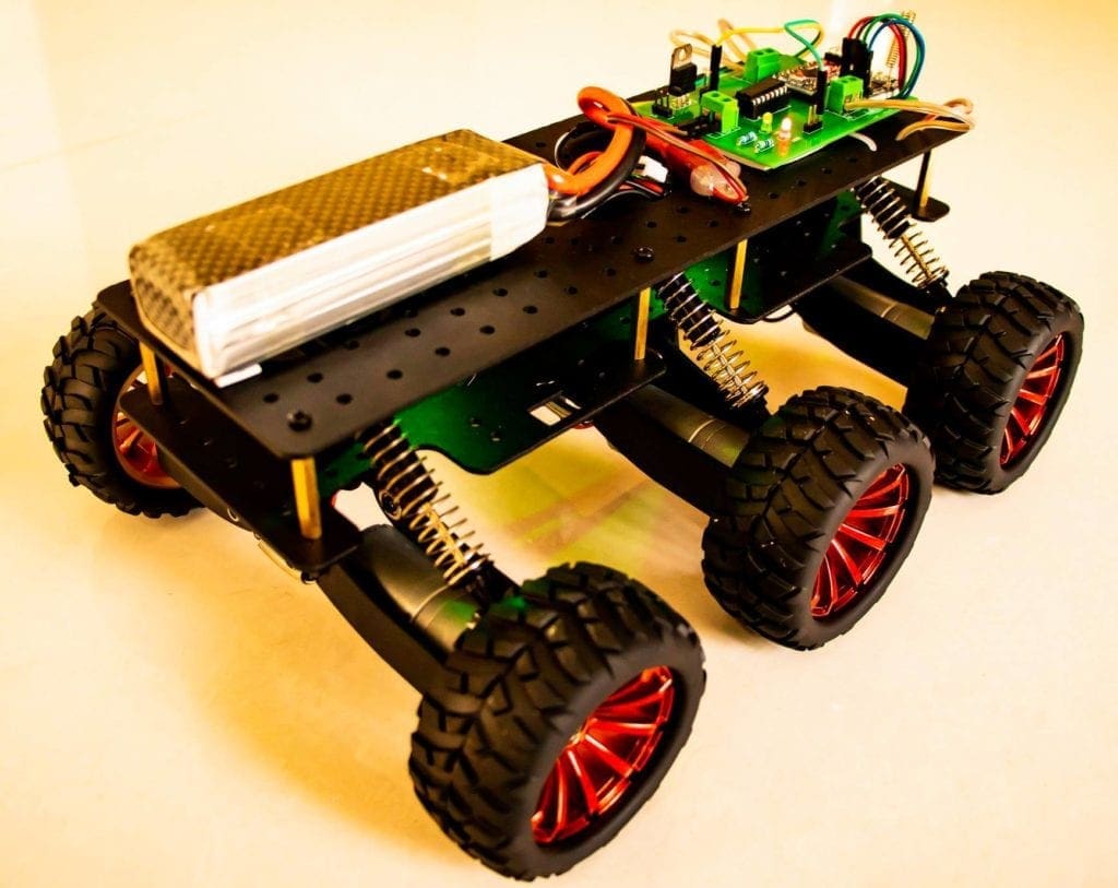
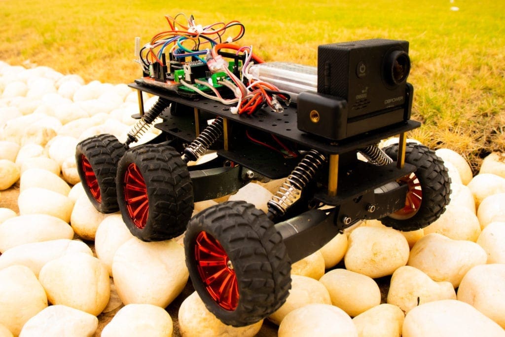
After that, I was building this 6-wheel drive RC robot with suspension as a hobby project. I used to make a lot of wheeled robots and so I already had some old PCBs I designed with Arduino Pro Mini, an HC12 wireless module, and an L293D motor driver IC.

Most of my previous robots were 2-wheeled or 4-wheeled and most of them had 2 or a maximum of 4 simple DC motors. So I didn’t have to worry about the current.
But this time it was different
It was the first time I was dealing with 6 high-speed DC motors using a single IC. These motors drew around 350 mA. I assembled the robot, and connected all the motors on one side to the output of Motor 1 of the L293d IC; similarly, I did with the other side. The connections were perfect.
What went wrong?
The problem started when I pushed the throttle. The bot moved like a snail and the motors made a humming sound. When I touched the IC, it was scorching. Single L293D was not able to provide enough current to drive all the motors.
So what’s next?
One solution was to use separate DC motor Drivers to drive the motors separately. Or I could use another motor driver IC – L298N – The Big Brother of L293D which can handle an output current of up to 2A. But the pin-out is entirely different and so you won’t be able to mount them in the place of L293D. I could also put one on top of the other and solder them in parallel which is called piggybacking, which I will explain in a moment.
Making a High Current DC Motor Driver
I decided to make a high current DC Motor Driver Shield for Arduino Nano that will be able to drive multiple motors simultaneously and independently and at the same time provide enough current to drive all of them without generating much heat.
DIY DC Motor Driver Shield for Arduino Nano – The Circuit
I used an Amazing PCB designer called Altium to make my own PCBs for my projects and believe me guys, It’s very easy to create our own PCBs using Altium. If you are a DIY electronic enthusiast, this is gonna be really useful for you! Altium is an Amazing PCB Designer with so many user-friendly tools and amazing features like centralized cloud storage, and online collaboration. You can design and create your own PCBs for your hobby projects or share your ideas across your network. You can download the free trial version from the description down below and also get a 6-month full license if you are a student! Check it out!

The idea here is to connect 2 L293D motor drivers in parallel. This is called L293d piggybacking. Let me explain it in simple terms. Let’s take a closer look at the L293D motor driver IC.
A little bit about L293D Motor Driver IC
L293D is a reduced type of H Bridge circuit in the form of an IC. L293D Motor Driver IC allows DC motors to drive in either direction without changing the physical circuit. It is an IC with 8 pins on each side (16 pins altogether) which contains 2 free H Bridge circuits. which means, we can control two motors separately utilizing a Single IC.

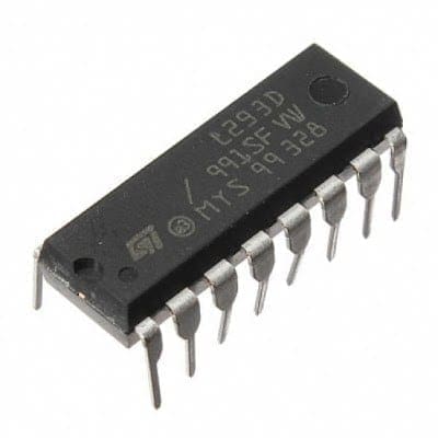
The left side of the IC deals with one H Bridge (One Motor) and the right side deals with the other. There is a pin called ‘Enable Pin’ for each H Bridge Circuits. The H bridge will work only if the Enable Pin is set to Logic 1. Due to the high current flowing through the circuit, there are 4 ground pins employed in this IC.
Limitations of L293D Motor Driver IC
Of course, L293D is the most widely used motor driver IC among hobbyists and engineers to drive DC motors in their projects. They are H Bridge circuits that can be used to control the direction as well as the speed of the motors.
But there are certain limitations to this L293D IC when it comes to High Load or High Current Motors. One of them is peak Current.
Check out the above piece of the datasheet. The maximum current it can provide over a single channel is 600 mA (1.2A Peak). With this current, L293D cannot drive multiple DC motors that draw a huge amount of current.
Piggybacking L293D Motor Driver IC for More Current
L293D piggyback configuration is an Easy Way to Double the Current as well as the power of L293D Motor driver IC, to drive a high torque/ high current motor or a high resistance load.

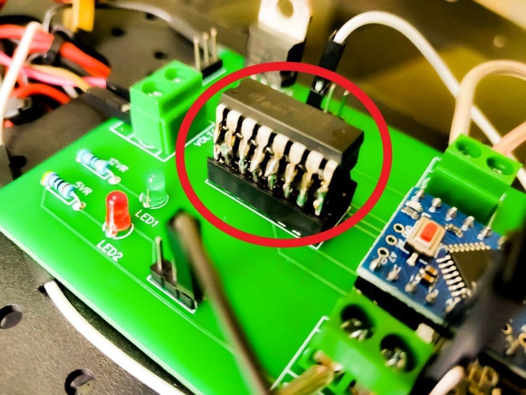
So the entire thought is to connect another L293D chip, straightforwardly over one IC, Pin to Pin, and thereby connecting them in parallel. This puts the two chips in the parallel mode so the voltage will remain the same as before but the current increases. These chips are evaluated at about 600ma constant or up to 1.2A for a brief period. After piggybacking two of them together, they will provide output with a 1.2A persistent current and a peak current of 2.4A for brief periods.
Back to the Motor Driver Circuit
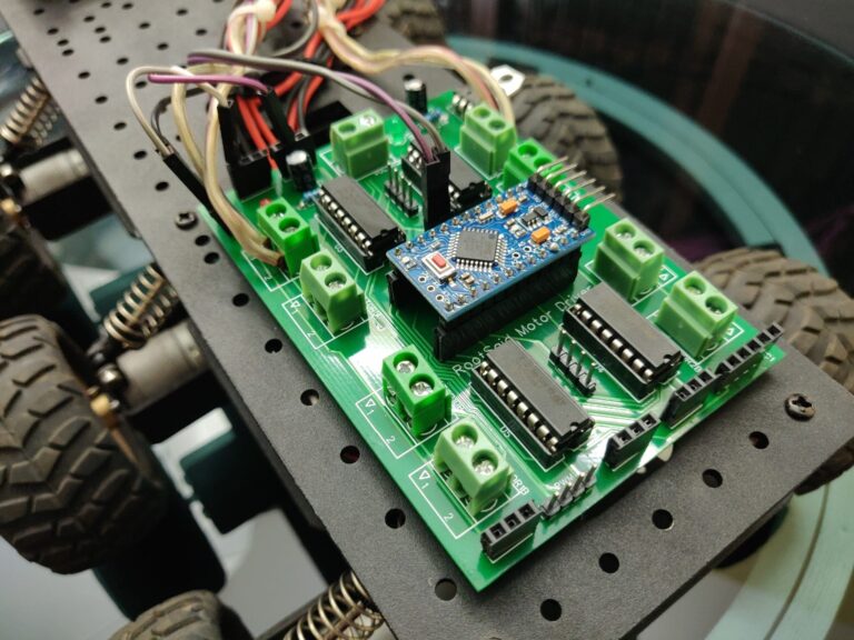
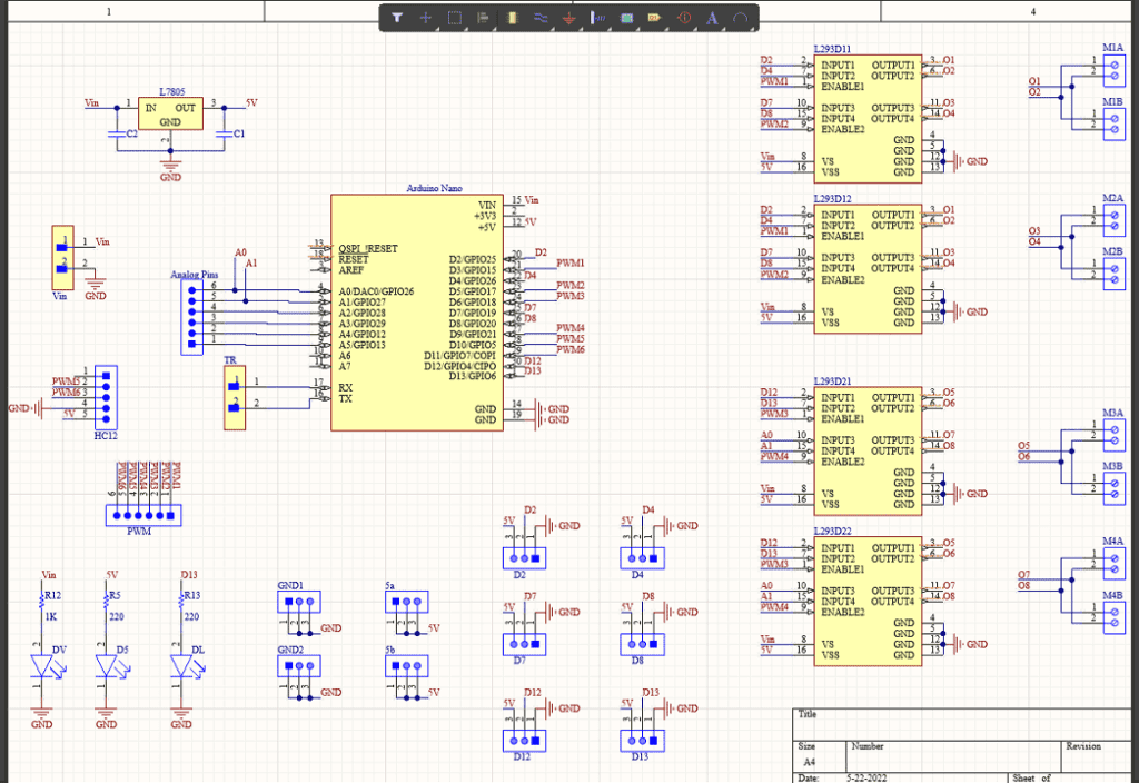
That’s what we did here. Here you can see a pair of L293d motor drivers connected in parallel over here and another pair of ICs connected in parallel over here. So the first pair ICs drive the first two motors and the second pair of ICs drive the next two DC motors.

All the inputs to l293d motor driver ICs are connected to GPIO pins and all the enable pins are connected to PWM pins of Arduino.
For IC Set 1, we use D2, D4, and D3 to control Motor1 and D7, D8 and D5 to control Motor 2
For IC Set 2, we use D12, D13, and D6 to control Motor 3 and A0, A1 and D9 to control Motor 4
Other than that, I have added some header pins over here which can be used to connect other sensors and modules to this board directly, and some more here that provide 5V and Ground connections which can be used to add power circuits to this board for further expansion.
Also, here is where we connect the HC12 wireless module which I will be using to control the bot remotely.
Also, I have added some indicator LEDs for easy troubleshooting.
PCB Layout and Design
Once the circuit was finished and tested, I designed a compact PCB using Altium, where I can fix all the components neatly. Here you can see routing is on both sides of the board which means it is a dual-layer PCB.

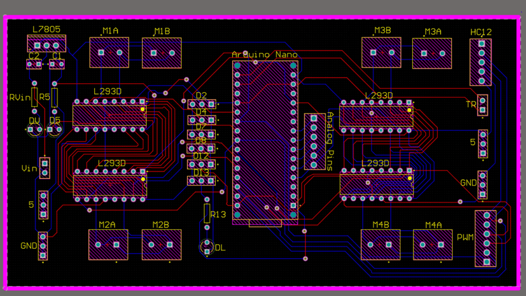
I will provide links to the Gerber file in the description.
Getting PCB Done
I ordered PCB from PCBWay. PCBWay is a PCB manufacturer specializing in PCB prototyping, low-volume production, and neat and tidy PCB assembly. If you are interested in making your own PCBs for your project, check out the link below. You can get a 5-dollar discount when you sign up using the link below and get an additional 5-dollar discount at the checkout by providing the coupon code PCBWayLab.

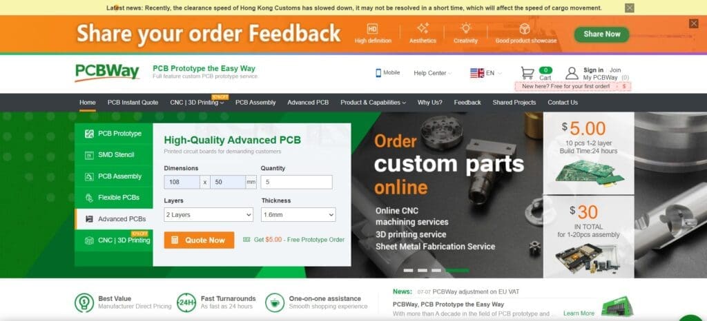
To order your PCB from PCBWay, go to the PCBWay website and fill in the basic board details in the instant order form. From there you will be directed to a form where you can provide more elaborate board details. Update your board information in the PCB specification screen. On the next screen, you should be able to upload your Gerber file and submit it for review. Once the review is completed, all that is left is to add to the cart, make payment, and wait for your PCBs to arrive.

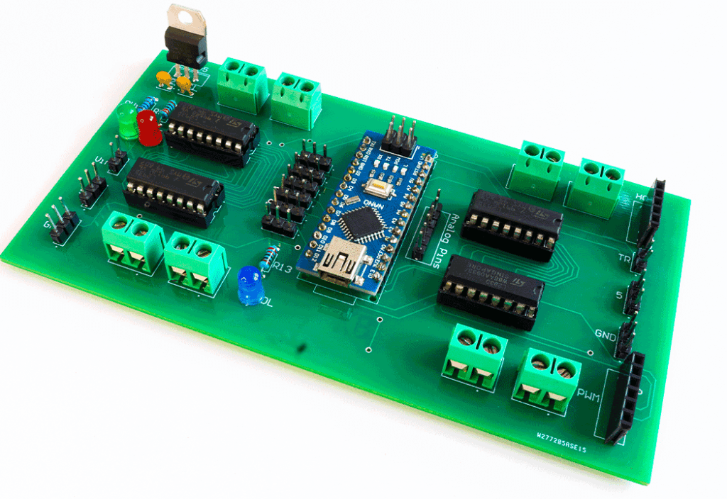
Once you get all the components and the PCB, it’s time for you to solder them together. Solder all the components onto the board and make sure to check the polarity of the components. After soldering the PCB looks like this.
Programming the DIY DC Motor Driver Shield
Now about coding the Arduino Nano for driving motors. Here, we are using Arduino Nano and we are not wasting any pins here. We have all the pins GPIO pins connected to these headers so that, if you want to connect any sensors or other external modules to this robot, you can do that easily with header cables like this.
To control motor 1, we can use pins D2 and D4, and PWM pins D3 to control the speed.
To control motor 2, we can use pins D7 and D8, and PWM pins D5 to control the speed.
To control motor 3, we can use pins D12 and D13, and PWM pins D6 to control the speed.
To control motor 4, we can use pins A1 and A0, and PWM pin D5 to control the speed
With this shield, you should be able to drive almost all the DIY robots that have up to 4 wheels easily.
You can also use the software serial library to receive the data from the HC12 wireless module from the remote controller and pass it on to Arduino.

Ask all your doubts in the comments down below. If you find this video useful, make sure you give this video a thumbs up. Subscribe to this channel for more awesome videos.