
H Bridge and L293D Motor Driver
H bridge is simply a circuit that allows a voltage to be applied across a load in either direction. They are commonly used for controlling DC motor in moving parts of robots. The advantage of using DC motor is that, we can reverse the polarity of applied voltage across the load without modifying the circuit.
Before going further, lets talk a little bit about DC motor.
DC Motor

As we all know, DC motor is a device that converts electrical energy to mechanical energy.
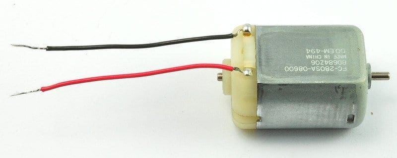
A DC motor has two terminals through which we apply the potential difference. When we apply potential difference across them, it will rotate in a particular direction, say clock wise. When we reverse the direction of the current, it will rotate in the opposite direction, that is anti clockwise direction. In short, if you want to change the direction of the spin of motor, all you have to do is reverse the polarity.
Working of H Bridge
H-bridge is a very small circuit. A simple H Bridge can be build by using any switching element such as BJT or FET. Consider the following circuit.
Here we have 4 transistors of which two of them in either side always acts as a complimentary pair. Complementary pair means when one turns ON the other turns OFF and vice versa.
Shown below is a simple version of the H Bridge circuit, here we have replaced the transistors with switches S1, S2, S1′ and S2′. Here, S1 and S1′ are complementary pairs and S2 and S2′ are complementary pairs.
Now consider various cases
Case 1 – S1 and S2 are Open (Zero)
When S1 and S2 are at logic zero, S1′ and S2′ will be in logic 1 since S1′ is the complement of S1 and S2′ is the complement of S2.
So overall, the circuit will be open. There won’t be any closed path for the current to travel.
Case 2 – S1 is Open and S2 is Closed
When S1 is Open, S1′ will be closed and when S2 is closed, S2′ will be Open.
Now the Current Flows from +V > S2 > M > S1′ > GND . And the motor rotates in one direction (say clockwise).
Case 3 – S2 is Open and S1 is Closed
When S2 is Open, S2′ will be closed and when S1 is closed, S1′ will be Open.
Now the Current Flows from +V > S1 > M > S2′ > GND . And the motor rotates in one direction (anti clockwise).
Case 4 – S1 and S2 are Closed (1)
When S1 and S2 are at logic One, S1′ and S2′ will be in logic Zero since S1′ is complement of S1 and S2′ is complement of S2.
So overall, the circuit will be open. There wont be any closed path for the current to travel. So the motor wont rotate
S1 S2 S1′ S2′ Direction
1 1 0 0 x
0 1 1 0 Clockwise
1 0 0 1 Anti Clockwise
0 0 1 1 x
L293D Dual H-Bridge IC
L293D is a compact form of H Bridge circuit in the form of an IC that employs the above-mentioned circuit. It is an IC with 8 pins on each side (16 pins in total) which contains 2 independent H Bridge circuits, which means, we can control two motors independently using a single IC.
L293D is a typical Motor driver or Motor Driver IC which allows DC motor to drive in either direction. L293D is a 16-pin IC that can control a set of two DC motors simultaneously in any direction. It means that you can control two DC motors with a single L293D IC.
As mentioned earlier, in an L293D IC, there are two H Bridge circuits. The left side of the IC deals with one H Bridge (One Motor) and the right side deals with the other. There is a pin called ‘Enable Pin’ for both the H Bridge Circuits. The H bridge will work only if the Enable Pin is set to Logic 1. Due to the high current flowing through the circuit, there are 4 ground pins employed in this IC.
One thing to keep in mind while using this IC is, there are two pins where we have to supply the input power. Pin 8 and Pin 16; are for entirely different purposes. Pin 9 is for driving the motor which can handle a voltage of 6 V to 30 Volt and Pin 16 will power up the IC for the internal circuit. Under no circumstances, you should not interchange these two pins or it may burn off the chip.
Speed Control Using PWM (Pulse Width Modulation)
As mentioned earlier, the enable Pin is the pin that controls the overall working of the H Bridge. When Enable Pin is set to High, the H Bridge will work normally, and when Enable Pin is set to 0, the motor won’t work no matter what other inputs are. So how will you control the revolution speed of the DC motor using this Pin? All you have to do is supply a PWM signal that will enable and disable the circuit in a periodic manner. This can be done using a 555 timer IC or a microcontroller like Arduino.