Arduino Remote Controlled Robot using HC12 Module
Hey guys, hope you all saw the demo of our latest Arduino Remote Controlled Robot.


In this post, I will be showing you how I built this wireless surveillance robot. I will give you the complete schematics, codes and complete layout of all the boards used in this Arduino RC Robot to make one yourself. So stay tuned!!
About our Sponsor
About our Sponsor
This project is sponsored by PCBGoGo. PCBGoGo is a PCB manufacturer specializing in PCB fabrication and assembly from prototype to mass production. They deliver high-quality bare and assembled PCBs faster and cheaper.


Celebrate 5th Anniversary with PCBGoGo
This month, PCBGOGO is celebrating its fifth birthday. To celebrate the anniversary, they are giving out a series of discount coupons. Souvenirs and wonderful offers to the new and regular customers (Campaign Deadline: Sep. 25th, 2020).

- Order Discount – Here you will find a collection of coupon codes that can be used for your next purchase.
- Souvenir Distribution – The customers who order more than $100 will get a chance to win these cool souvenirs like PCB Ruler, Eco-tote Bag, Stylish Pen.
- Sharing Benefit – Each one who shares this anniversary good news and tag 3 friends will get a 5$ Coupon.
Though PCBGOGO is only 5 years old, their factories, with over 400 workers now, have been providing PCB fabrication and assembly for domestic customers in China for more than 10 years. Till now, their daily PCBs and PCB assembly order quantity exceeds 3000, and the sales have increased from $100,000 to $20 million a year.
Do remember that, PCBGOGO always welcomes your PCB manufacturing and assembly sample order when you start a new project. Don’t miss it.
Arduino Remote Controlled Robot Demo
First let us take a look at our Arduino Off Road Robot and how it performs in rough terrain.
Looks Cool Right? Now let us take a look at the components used one by one.
Getting Started with Robotics?
Want to learn Robotics from Scratch? Here is an awesome guide for you to get started with robotics (Free Video Tutorials Included).
6 Wheel Drive Arduino Remote Controlled Robot Components – Get Your Components
- Robot Chassis – Get it Now
- Arduino Pro Mini – Get it Now
- HC12 – Get it Now
- Remote Controller
- VNH2SP30 Motor Driver
- LiPo Battery – Get it Now
I will try to make this video as simple as possible so that you can understand everything easily in a fun way.
Let’s get started. First I will be giving you guys a short summary of what we are going to do in this lesson.
Here, we will be having a remote controller and a robot.
In the remote controller we will gather user input using a joystick, accelerometer and some switches. Using an arduino, we combine them into a long string of data and are transmitted to the robot using the HC12 wireless module.
On the receiving side, the HC12 in the robot’s circuit will receive the signal, separate them, store them in variables, and use these variables to drive the motors.
Lets get familiarised with the components.
The Components
Here, we will be using HC 12 wireless module for transmitting data from the DIY Remote Controller to the RC Robot. They are commonly used in remote controlled robots and other wireless communication projects. This wireless module works under 433 megahertz frequency. When combined with an external antenna, this wireless module can transmit and receive data from a distance of up to 1 Kilometer line of sight and due to this reason we will be using this wireless module for our robot.

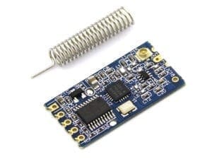
This wireless module can be easily connected to arduino or Raspberry Pi, and start using it for your project right away. Another advantage of using HC12 wireless module for your RC robot is, this module requires only two pins – TX and RX, for data transfer. You can save the rest of the pins of your arduino or Raspberry Pi for other things.
As I mentioned earlier this robot chassis have 6 high speed DC Motors with a speed of 17000 RPM combined with 1:34 metal gear box. Each motor draws a current of about 350 milli ampere. As you might know, for almost all of my Robots, I use either L293D motor driver or L298N motor driver.
Here also I tried L293D and L298N Piggybacked. Even though it worked fine, too much energy was wasted as heat after 5 minutes of continuous usage.

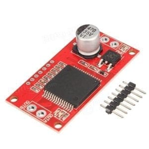
So I decided to go for another high current motor driver, named VNH2SP30, that can provide a peak current of 30 amperes.
If you are not familiar with this VNH2SP30 High Current DC Motor Driver, please click this link you know more about it.
This motor driver board can control only one motor at a time. So here we will be using two motor driver board to control both DC motors.
Powering up the Off Road Robot
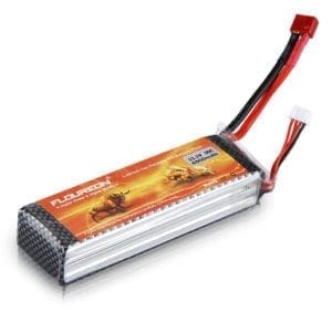
For this project I’ll be using a 12 volt Lithium polymer battery as a power source. This can provide enough power to drive all the six DC Motors, power up the arduino, HC12 module and the motor drivers without any issues.
Thats all you need to know about all the components used in this off road RC robot. started with making the robot.
Joystick
This is one of the most commonly used analog joystick modules which is designed to work with Arduino. It has two analog potentiometers – one detects the vertical motion of the joystick and other detects the horizontal movement of the joystick. This is really cheap and can be used for various projects like RC cars, video game joystick.
For simplicity, in this projects, we will only be using the joystick.
Accelerometer
An Accelerometer is an electromechanical device that measures the force of acceleration due to gravity. It can be used in applications requiring tilt sensing. The ADXL335 measures acceleration along X, Y and Z axes and gives analog voltage output proportional to the acceleration along these 3 axes. I will show you how to use this accelerometer in the next project.
Arduino Remote Controlled Robot – The Remote controller
In my previous video, I showed how you make this Wireless Remote Controller for your RC Robot using a breadboard accelerometer, buttons, and an HC12 wireless module. If you haven’t seen that yet, please see the below video first. Because we will be using that remote controller to control this robot.

Basically what this remote controller does is, it reads analog and digital data from sensors such as accelerometer buttons joystick and store them in separate variables. These variables will be combined together to form a single long string and this string will be sent to our robot using the HC12 wireless module.
Circuit
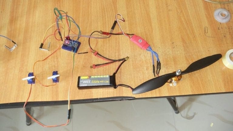
I made a circuit which included all the components: the joystick, accelerometer, arduino nano and hc12 module connected to the GPIO pin of the arduino and assembled it on a breadboard.


It worked flawlessly but the problem was, the whole board looked really messy with all the jumper wires going here and there. So I decided to go with PCB.
In the PCB version, I added 4 switches which I will be using for the next project.
I also added a 7805 regulator which will help me to provide an input voltage between 7V and 35V so that I can use a 5V USB power supply, 9V battery or even 12 V Lipo battery without any issues. I also added some indicator LEDs that will let me know if something stopped working. You will find the circuit in the link below.
I will share the circuit diagram and PCB file in the description.
Coding
Now it’s time to upload the code. This is the code. I will share the link in the description, you can simply copy and paste the code and upload it to your controller.

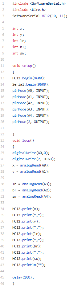
Basically, what this code do is, it will start a software serial connection at pin 10 and 11 where we connect the Tx and Rx pins of HC12 wireless module. Arduino will read the analog voltage of the pins A0 – A4 where we connect the sensor inputs (accelerometer and joystick) and store their values in different variables. Then it will create a single long string by combining all the data which will then be send to the Remotely Controlled Robot.
Once you are done uploading, open up the serial monitor.
You will see all the sensor data that is being read by the Arduino as a Single line separated by commas ( , ). This is how our data will be sent to the Remote Robot.
The Robot
Now it’s time to receive the data from the remote controller. In the receiving unit, I used an Arduino nano clone and another HC12 as receiver.


You can use any motor driver board to drive the motors in the robot. This robot chassis have 6 high speed DC Motors with a speed of 17000 RPM. Each motor draws a current of about 350 milli ampere. As you might know, for almost all of my Robots, I use either L293D motor driver or L298N motor driver.
Since we have 6 DC motors, I decided to go for another high current motor driver, named VNH 2SP30, that can provide a peak current of 30 amperes.
If you are not familiar with this VNH2SP30 High Current DC Motor Driver, please click this link to know more about it.
This motor driver board can control only one motor at a time. So here we will be using two motor driver boards to control all the DC motors. I will share the circuit diagram in the link below.
Assembly
Now let’s start making our RC Robot.
As mentioned earlier, this off road robot chassis is a DIY kit; which means it will need some assembly to get started with. When you open the packet you will see all the components and tools neatly labelled. You won’t need more than half an hour to set this up. You can check out this video if you are stuck and need help assembling the robot.

Once the robot chassis is assembled, you can start fixing all the components onto the top plate. You can use screws, glue gun or double sided tape to secure all the components onto it.
The Circuit
Next step, Connecting all the components together. We will connect the HC12 module to the Arduino, which will process the data coming from the HC12 module of the Remote controller.
Once the data is processed, we will drive the motors using the high current DC motor driver connected to the Arduino. The whole circuit will be powered using the LiPo battery.
Connections for the Circuit of RC Robot
Arduino —— HC12
- 5 Vout – VCC Arduino
- Gnd – Gnd
- 10 – TX
- 11 – Rx
Arduino —– Motor Drivers
- Pin 12 – Motor Driver 1 In1
- Pin 13 – Motor Driver 1 In2
- Pin 3 – Motor Driver 1 PWM
- Pin 8 – Motor Driver 2 In1
- Pin 7 – Motor Driver 2 In2
- Pin 5 – Motor Driver 2 PWM
Motor Drivers —– Motor
- Motor Driver 1 Out 1 – Motor 1 Terminal 1
- Motor Driver 1 Out 2 – Motor 1 Terminal 2
- Motor Driver 2 Out 1 – Motor 2 Terminal 1
- Motor Driver 2 Out 2 – Motor 2 Terminal 2
- Motor + – 12 V
- Motor – – 0 V
- Vcc – 5 V
- Gnd – 0 V
Here, you will find complete Circuit of the Remote Controller
The Code
Here, I will share the code for HC12 Remote Controller and the RC Robot. Simply upload this code to your remote controller as well as your DIY RC Robot.
This is the code for DIY RC Off Road Robot
Arduino RC Robot Code Download
First, we read the data coming from the receiving module to a variable named ‘input’. This ‘input’ is a long string of decimal numbers separated by commas. This string is broken down into smaller numbers and is then stored in separate variables.
These values can be used to control the Robot the way you want.
You can now use these variables to drive your robot the way you want.
Testing
Once the code is uploaded you can power up the entire robot put it on the floor and try moving the joystick. Its fun right?
That’s it guys. Have fun. Play with it.
Top Arduino Projects You can Try this Summer Vacation

Top Robotics Projects You can Try this Summer Vacation

Did you find this page useful? Help us to improve by rating this page.
[RICH_REVIEWS_FORM]
[RICH_REVIEWS_SNIPPET stars_only=”true”]