Pick and Place Robot Arduino Tutorial | Make a DIY Robot

Hope you have gone through the introduction part of the Spinel Crux L2 – Arduino Pick and Place Robot with Robotic Arm. Looks cool under glowing lights right? Why not build one for yourself? Here we will learn how to build a robot and connect a robotic arm on top of it and build our own DIY pick and place robot.
We will provide you with the design, code, circuit diagrams, and links to buy your own robotic arm, robot kit, chassis and sensor modules used in this project.
Try to make one yourself and if you are stuck with the project, you can always contact us or ask your questions in the comment box or in our WhatsApp group. So without further ado, let get started with the project!
Arduino Pick and Place Robot Video Tutorial
First take at the video of the Pick and Place Robot we have made.

First let me tell you a little bit about the components I used to build this pick and place robot.
Arduino Pick and Place Robot Components Needed
Accelerometer

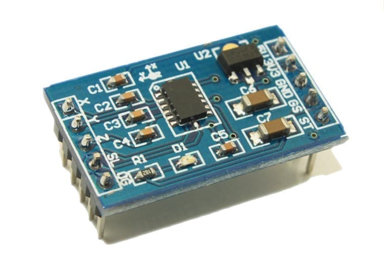
An accelerometer is a sensor which can be used to sense the acceleration due to gravity on various axis acting on an object. Using this we can easily calculate the tilt of an object with respect to the Ground. We will driving our Spinel Crux using the X and Y tilt analog values.
Here I am using MMA7361 accelerometer to control the direction of our Gesture Controlled Robot; you can use any accelerometer which will give analog values in X and Y direction. The reason why I am using this accelerometer is, we can provide 5 volts as well as 3.3 volts as Vcc to this accelerometer. since I am using Arduino MKR1000, I can connect 3.3 Volt directly from the Arduino. It is also small very lightweight and can easily be connected to Arduino and Raspberry Pi without much complication. if you want you can buy this accelerometer for a cheap price from banggood.com.
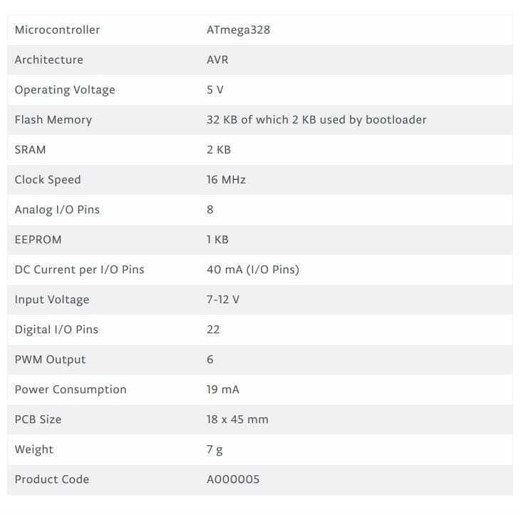
Arduino Nano
In this project we will have to use two micorcontroller – one for the controller which will gather all the sensor data and transmit them to the wireless module and another one on the robot, which will gather data from the receiver module, process them and control robotic arm and the pick and place robot. The Arduino Nano is very small and can easily be fitted on top of the bread board. This can be easily programmed using a PC via USB using Arduino IDE
This board can be powered using the Mini USB port. Through pin 30, we can supply an unregulated voltage source of 6 to 20V or through pin 27, we can provide a regulated power source of 5V. The power selection will be automatically done by the Nano board.
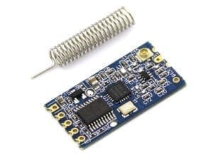
HC12
HC 12 is a really cheap long-range wireless module that can be used for wireless serial communication over a long distance of up to 1.7 KM. The module is really compact lightweight and breadboard-friendly which makes this the best wireless controller for our project.

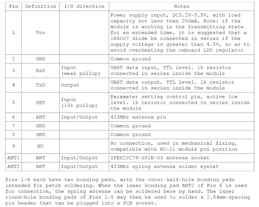
Pinout

Testing HC12 Connection
#include <SoftwareSerial.h>
SoftwareSerial HC12(10, 11); // HC-12 TX Pin, HC-12 RX Pin
void setup() {
Serial.begin(9600); // Serial port to computer
HC12.begin(9600); // Serial port to HC12
}
void loop() {
while (HC12.available()) { // If HC-12 has data
Serial.write(HC12.read()); // Send the data to Serial monitor
}
while (Serial.available()) { // If Serial monitor has data
HC12.write(Serial.read()); // Send that data to HC-12
}
}
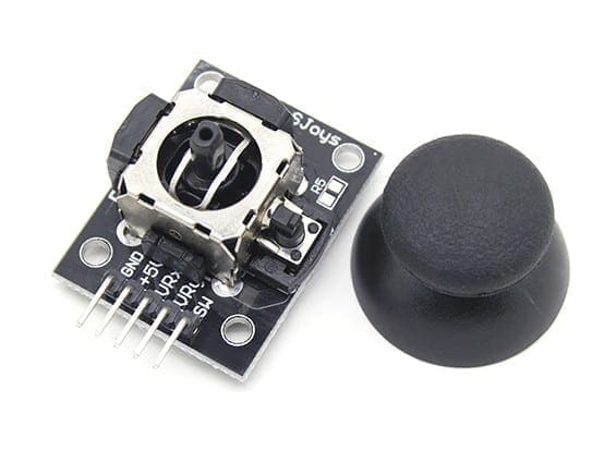
Joystick
This is the most widely used robotic controller which comes with various robot DIY robot kit/robot arm kit that is built to work with arduino. The design is quite simple and is very easy to use. It uses two potentiometers to calculate the motion in the x axis and y axis and a switch to sense the button press.
This can be easily connected to the arduino’s analog pins and read analog values directly.

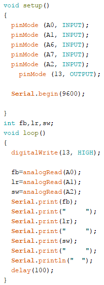
Before uploading the main code, make sure your joystick works by using this code. Download the code from the above link. In this example, what we are doing is simply collecting the data analog outputs from the Joystick using the analog pins (A0, A1,A2) of arduino. These values are stored in the variables and are later printed on the serial monitor.
We will divide this post into two parts
1- Pick and Place Robot Remote Controller
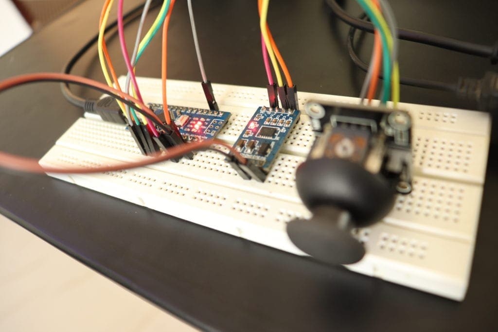
The Transmitter consist of a breadboard in which we mount all the sensors and components to get the data which is used to drive the pick and place robot and the robotic arm. This includes an accelerometer, a joystick, and an HC12 module.
We will use the accelerometer to control the robotic arm and joystick to control the robot. For now, we will use the joystick button to close the robotic hand. The data from this sensors are transmitted wirelessly to the DIY robot using an HC12 module.
2- The Pick and Place Robot

Here, I will tell you how to make a robotic arm, build a robot and mount the arm on top of the robot. You will also learn how to program Arduino to read the data coming from the wireless communication module – HC12, process it, and how to remote control the robotic arm with Arduino along with the robot.
Part 1 – The Remote Controller
What it does?
As mentioned earlier, this DIY Robot is a remotely controlled robot. So in the controller section, we have a breadboard, a joystick – to control the movement of the robot and the closing and opening of the fist of the robot, an accelerometer – to move the robotic arm, and a wireless module to transmit this data to the robot.
Connections

Simply connect all the components as shown below. We will be powering the Arduino with a 5V power bank and use the 5 V Vout of the arduino to power up all the other modules.
The Remote controller PCB
In my previous video, I showed how you make this Wireless Remote Controller for your RC Robot using a breadboard accelerometer, buttons, and an HC12 wireless module. If you haven’t seen that yet, please see the below video first. Because we will be using that remote controller to control this robot.
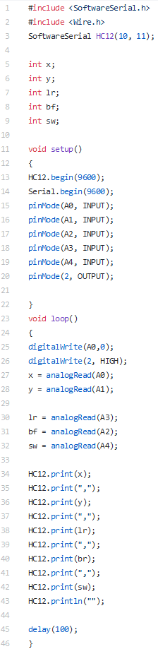
Basically what this remote controller does is, it reads analog and digital data from sensors such as accelerometer buttons joystick and store them in separate variables. These variables will be combined together to form a single long string and this string will be sent to our robot using the HC12 wireless module.

Drawing Schematics and PCB Design using Altium
So I used Altium Designer to draw the circuit and design the PCB. It is a powerful tool that can be used to design and create your own PCBs for your project as well as complex and multiplayer PCBs for industrial use. Here is the link to the Altium trial version. So make sure you check it out.
Circuit
I made a circuit which included all the components: the joystick, accelerometer, arduino nano and hc12 module connected to the GPIO pin of the arduino and assembled it on a breadboard.


It worked flawlessly but the problem was, the whole board looked really messy with all the jumper wires going here and there. So I decided to go with PCB.
In the PCB version, I added 4 switches which I will be using for the next project.
I also added a 7805 regulator which will help me to provide an input voltage between 7V and 35V so that I can use a 5V USB power supply, 9V battery or even 12 V Lipo battery without any issues. I also added some indicator LEDs that will let me know if something stopped working. You will find the circuit in the link below.
PCB Layout
Altium PCB designer can also be used to make PCB layout. This is the layout I made using the circuit. As you can see this is a dual-layer PCB, which means routing is there on both sides – the top side as well as the bottom side.


On the left side of the board I left some empty space to keep my batteries Now I have the Gerber file with me. All I had to do is order the PCB.
Once I got all the components, I soldered them all together and this is my final PCB. You see, all the components are connected to the board now.
int x;
int y;
int lr;
int bf;
int sw;

void setup()
{
Serial.begin(9600);
pinMode(A0, INPUT);
pinMode(A1, INPUT);
pinMode(A2, INPUT);
pinMode(A3, INPUT);
pinMode(A4, INPUT);

pinMode(2, OUTPUT);

}
void loop()
{
digitalWrite(A0,0);
digitalWrite(2, HIGH);
x = analogRead(A0);
y = analogRead(A1);

lr = analogRead(A2);
bf = analogRead(A3);
sw = analogRead(A4);

Serial.print("Accelerometer");

Serial.print("X = ");
Serial.println(x);
Serial.print("Y = ");
Serial.println(y);
Serial.println("");

Serial.print("Joy Stick");
Serial.println("");

Serial.print("Left/Right = ");
Serial.println(lr);
Serial.print("Back/Forward = ");
Serial.println(bf);
Serial.print("Switch = ");
Serial.println(sw);
Serial.println("");
Serial.println("");

delay(250);
}
Once this code is uploaded, start the serial monitor and check if all those values are shown properly.
Then you can upload the real code below.
Code
Simply download the below code using the download link below and upload it to your controller.

Part 2 -The Robot
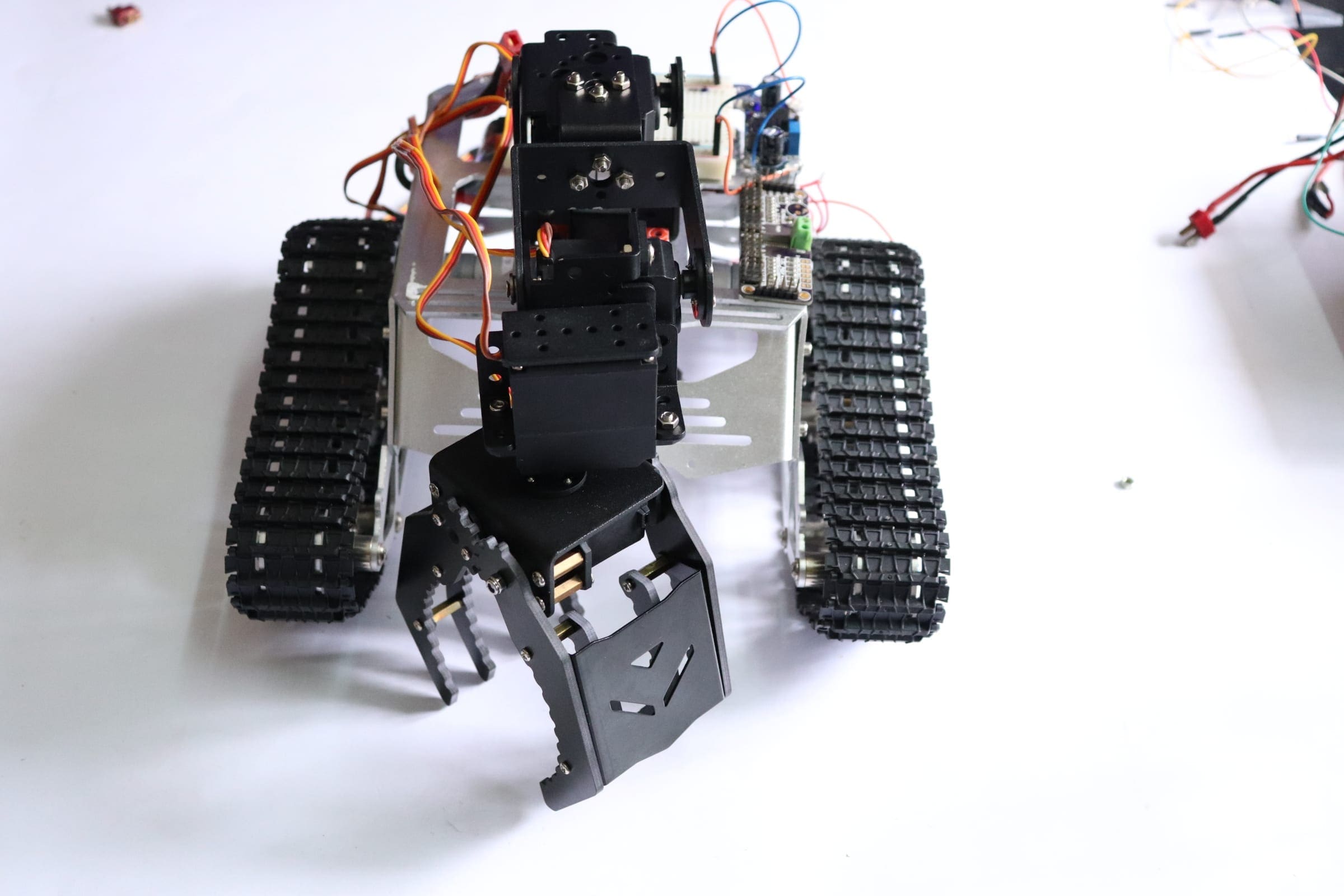
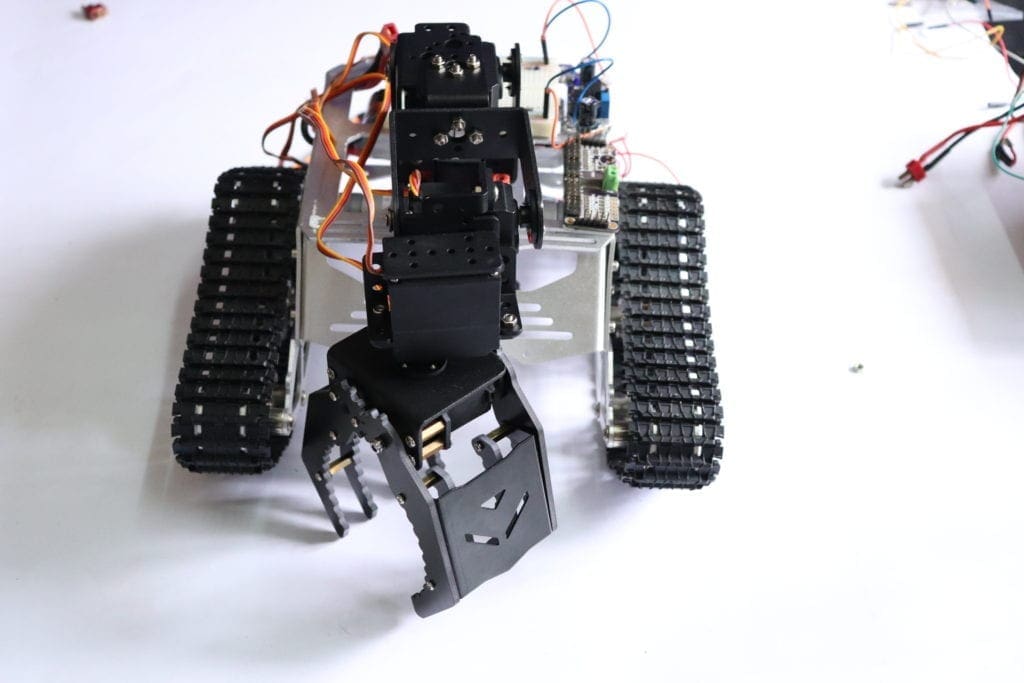
The main part of the robot is the chassis in which we mount all the components including the arm.
I got the robotic arm kit from banggood.com. This robotic arm is made of good quality aluminum and is really light weight. This one have so many mounting points which will allow us to connect to any robot bodies/chassis without drilling mounting holes.

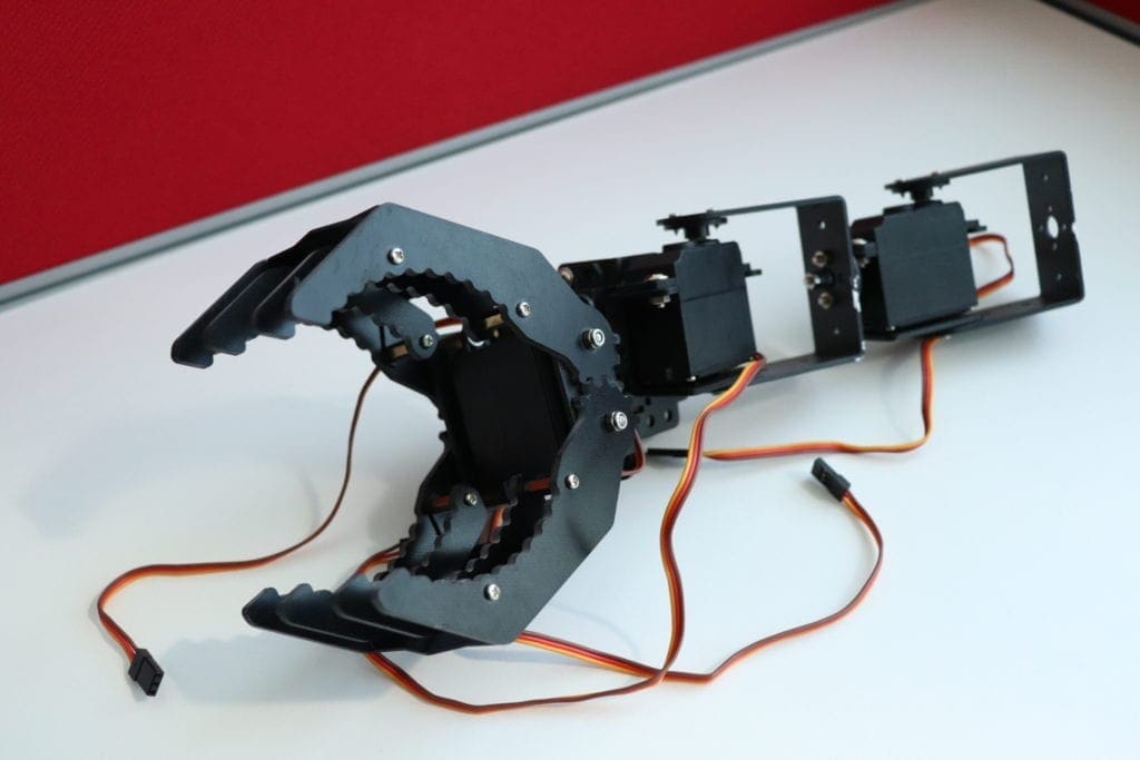
There are 4 servo motors which will give the robotic arm a total of 3 Degrees of Freedom. The servo motors are included and the working voltage is 4.8-6V.
You can either buy this along with the servo motor or you can buy them separately.
The chassis I used for making this pick and place robot is something I would like to talk about. I got this kit banggood.com. Not only this one, they have so many types of robot frames, motors and almost all the sensors for doing Arduino, raspberry pi and other electronics and hobby projects. You will get all these things for a cheap price with really fast and quality shipping.
And the great thing about this kit is they provide all the tools you need to assemble the frame together.
Get your DIY Robot Kit From BangGood
Servo Motor Control
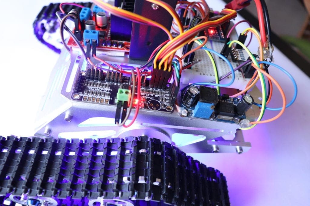
The PCA9685 is a 16 Channel 12 Bit PWM I2C-bus controlled Servo motor Driver. The Driver can very easily connected to your arduino, Raspberry Pie and easily programmed to control single or multiple servo motors and make your own RC plane, car, ship, quadrapod, hexapod or anything you want.
Follow this link to know more about the servo motor driver.
Pick and Place Robot – Connections
Here we will be using a 12 V power supply for powering up the entire robot. We feed the raw 12 Volt to the LED and the motor driver IC voltage in for motor.
Then we use a regulator to step down voltage to 5V and feed it to Arduino, HC12 and Servo motor driver.
You can drive the DC motors using using a good motor driver IC. In this project, I will be using Dual H Bridge Motor Driver IC – L293D which can control two servo motors at a time.
For more details on driving DC motors using L293D IC click here. If you are new to this, it is better to go through this before proceeding to the next step to get a better understanding of the project.

Simply connect all the components as shown below.
We will be powering the Arduino with a 5V power bank and use the 5 V Vout of the arduino to power up all the other modules.
Arduino – Servo motor Driver
- 5 Vout – VCC Arduino
- Gnd – Gnd
- SDA – SDA
- SCL – SCL
Arduino – HC12
- 5 Vout – VCC Arduino
- Gnd – Gnd
- 10 – TX
- 11 – Rx
Servo motor Driver – Servo Motor
- Servo 1 – Port 000
- Servo 2 – Port 001
- Servo 3 – Port 002
- Servo 4 – Port 003
Arduino – L293D
- Pin 2 – Motor 1 A
- Pin 3 – Motor 1 B
- Pin 4 – Motor 2 A
- Pin 5 – Motor 2 B
L293D
The H bridge will work only if the Enable Pin is set to Logic 1
One thing to keep in mind while using this IC is, there are two pins where we have to supply the input power. Pin 8 and Pin 16; both are for entirely different purposes. Pin 9 is for driving the motor which can handle a voltage of 6 V to 30 Volt and Pin 16 which will power up the IC for the internal circuit. Under no circumstances, you should not interchange these two pins or it may burn off the chip.
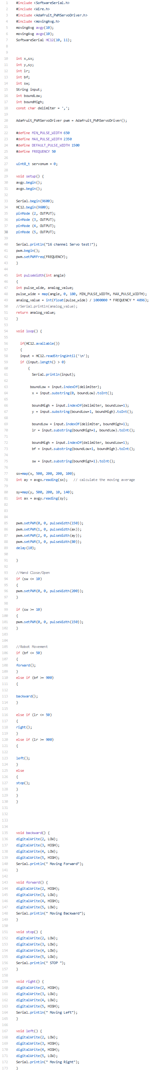
Code
Simply download the below code using the download link below and upload it to you DIY robot and you will be good to go.

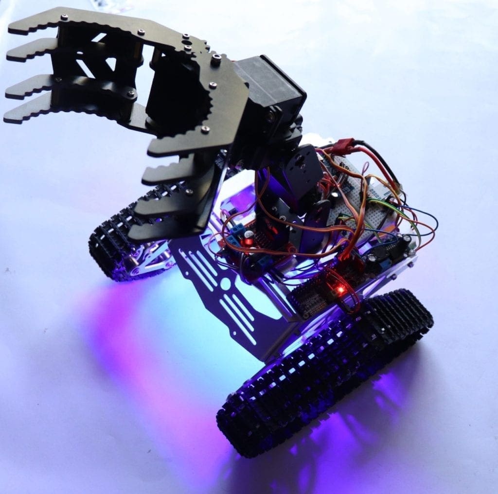
Lets Ride!!!
Once the code is uploaded to your pick and place robot, you can connect your robot to a 12 V power source and your robot wireless controller to a 5V power source.
Now you should be able to control the robot remotely using the wireless controller.
Whats next?
This is just a beginning. We, the RootSaid group is working on a wireless control glove that can be used to control the whole robot, including the robotic arm. But there is something cool about this glove.
This glove can detect hand gestures WITHOUT Flex sensor. Yes, you heard that right. Want to find out more? Be a part of RootSaid.
Subscribe RootSaid Website by simply entering your Email ID below. You will receive notification whenever the tutorial is available for you to tinker with.