NodeMCU – Set up Arduino IDE and Start using WiFi
IOT is one of the worlds largest and fastest growing technologies.In this post, I will explain a new standalone module based on ESP8266 WiFi SOC, I will be explaining everything you need to know about Node MCU.

Sponsor Link
This Project is Sponsored by UTSource. UTSource is a professional electronic components supplier.
What is NodeMCU?
Node MCU is an open-source platform that is specifically designed for IoT projects. This tiny little board is based on the ESP8266 WiFi module which is specifically designed for working with or without microcontrollers that uses Lua scripting language. This module has 10 GPIO, all of which can be used as PWM, IIC, 1-Wire and Analog to Digital Converters all in one board. It also has a PCB antenna etched in the board, which significantly improves the connectivity.
This little board can be easily programmed using the worlds most user friendly Open Source Platform – Arduino. This will be explained in detail below.
Node MCU Pinout
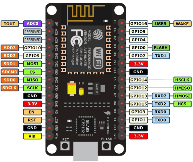
| IO index | ESP8266 pin | IO index | ESP8266 pin |
|---|---|---|---|
| 0 [*] | GPIO16 | 7 | GPIO13 |
| 1 | GPIO5 | 8 | GPIO15 |
| 2 | GPIO4 | 9 | GPIO3 |
| 3 | GPIO0 | 10 | GPIO1 |
| 4 | GPIO2 | 11 | GPIO9 |
| 5 | GPIO14 | 12 | GPIO10 |
| 6 | GPIO12 |
Setting Up Node MCU in Arduino
Step 1 – Download Arduino IDE from the below link.
https://www.arduino.cc/en/Main/Software
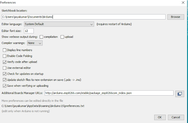
Step 2 – Once the Download is finished Open Arduino IDE, go to Files>Preference. In the ‘Additional boards manager URLs’, copy and paste the below line as shown in the screenshot
http://arduino.esp8266.com/stable/package_esp8266com_index.json
Step 3 – Once it is done, Go to Tool > Board > Board Manager
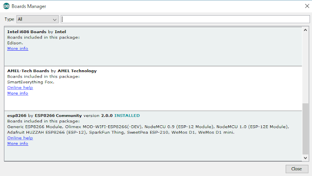
In the search box, type ESP8266 and install the board.
Uploading the Code
Now choose the correct board and port and set baudrate to 9600 (depends up on your firmware). Connect an LED to D7 pin of Node MCU which is mapped to pin 13. Copy and paste the below code to arduino IDE to test if it is working.
void setup() {
pinMode(13, OUTPUT);
}void loop() {
digitalWrite(13, HIGH);
delay(1000);
digitalWrite(13, LOW);
delay(1000);
}
If you have donw everything correctly, the LED will start to glow.
Connecting Node MCU to your WiFi Network
Now lets go one more step further. The below code connects the NODE MCU module to your wifi network and starts a web server at port 80 which can be accessed by any web browser. Now we are going to turn on or off the led from the browser.
#include <ESP8266WiFi.h>
const char* ssid = “rootsaid”; //Enter your Wifi name
const char* password = “rootsaidpassword”; //Enter your Wifi Password
int ledPin = 13;
WiFiServer server(80);void setup() {
Serial.begin(9600);
delay(10);
pinMode(ledPin, OUTPUT);
digitalWrite(ledPin, LOW);// Connect to WiFi network
Serial.println();
Serial.print(“Connecting to “);
Serial.println(ssid);WiFi.begin(ssid, password);
while (WiFi.status() != WL_CONNECTED) {
delay(500);
Serial.print(“Scanning…. “);
}
Serial.println(“”);
Serial.println(“WiFi connected”);// Start the server
server.begin();
Serial.println(“Server started”);// Print the IP address
Serial.print(“Use this URL to connect: “);
Serial.print(“http://”);
Serial.print(WiFi.localIP());
Serial.println(“/”);
}void loop() {
// Check if a client has connected
WiFiClient client = server.available();
if (!client) {
return;
}// Wait until the client sends some data
Serial.println(“new client”);
while(!client.available()){
delay(1);
}// Read the first line of the request
String request = client.readStringUntil(‘r’);
Serial.println(request);
client.flush();// Match the request
int value = LOW;
if (request.indexOf(“/LED=ON”) != -1) {
digitalWrite(ledPin, HIGH);
value = HIGH;
}
if (request.indexOf(“/LED=OFF”) != -1) {
digitalWrite(ledPin, LOW);
value = LOW;
}// Set ledPin according to the request
//digitalWrite(ledPin, value);// Return the response
client.println(“HTTP/1.1 200 OK”);
client.println(“Content-Type: text/html”);
client.println(“”); // do not forget this one
client.println(“<!DOCTYPE HTML>”);
client.println(“<html>”);client.print(“Led pin is now: “);
if(value == HIGH) {
client.print(“On”);
} else {
client.print(“Off”);
}
client.println(“<br><br>”);
client.println(“<a href=”/LED=ON””><button>Turn On </button></a>”);
client.println(“<a href=”/LED=OFF””><button>Turn Off </button></a><br />”);
client.println(“</html>”);delay(1);
Serial.println(“Client disonnected”);
Serial.println(“”);
Once you have uploaded the program, check the serial monitor on top of arduino IDE.
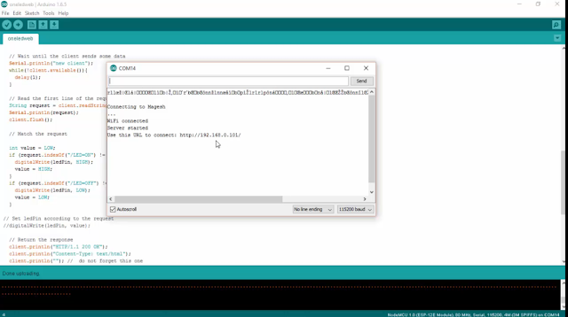
This will give the IP address of the module. Now open up any browser and issue that IP address. Thats it guys. Have fun.


Nice Project!! Maybe you could give me a hint. When i connect the MCU with a USB Cable to my Computer the Chip work but if i Setup a 3.3V Power Connection without a USB Cable then the WiFi is not available. Have you any Idea whats going wrong?