ESP8266 WiFi IOT Module Explained
The sudden drop in price of IoT modules and rapid growth of Internet of Things is allowing hobbyists to create new devices at home.ESP8266 is one such module which is specifically designed for IoT projects and costs less than 5$. This module can be used with or without micro-controller.


Sponsor Link
This Project is Sponsored by UTSource. UTSource is a professional electronic components supplier.
What is ESP8266?
As mentioned above, ESP8266 is a tiny, cheap but powerful WiFi module that was launched in 2014, which allows microcontroller boards like Arduino to connect to a wifi network and make a connection to the network and internet.[AdSense-B]The ESP8266 comes with a pre-installed firmware which allows us to send AT commands and Receive the Responses.
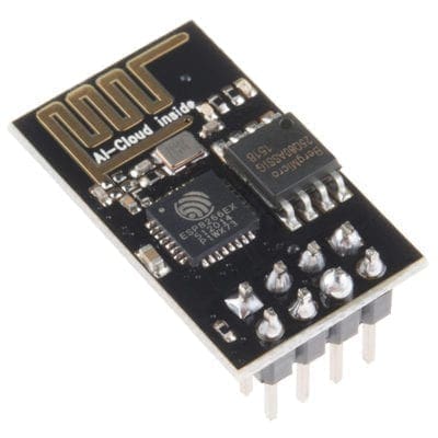
ESP8266 Pinout

ESP8266 board has 8 pins in total. The first pin on the top right is GND, the below two pins are GPIO 2 and 0. The bottom right we have RX pin and the pin on the lower left is VCC. The middle pins on the right are CH_PD(chip power-down) and RST(reset) and on top left we have TX Pin. We will be using TX and Rx Pins for communication.
For normal operation, CH_PD and the RST pins must be set to high (3.3V).
Note : The ESP8266 requires 3.3V power voltage (Even the tx and rx pins) and peaks at 500mA current for short period of time. Most of arduino boards and USB to serial converters works under 5 V.[AdSense-C] So you should always use a logic converter before connecting this module. You can use a FTDI232R converter, which will convert 5V to 3.3V.
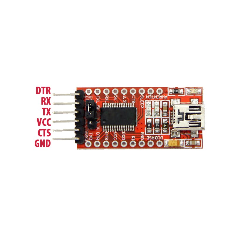
The Connections
ESP8266 FTDI232
- VCC 3.3V
- Gnd Gnd
- TX RX
- RX TX
- CH_PD 3.3V
- RST 3.3V
Now you can connect the FTDI module to your computer. You can either use Arduino or Putty for sending AT commands to the module. Set baud rate to 115200 because most of the time, that will be preconfigured. If it doesn’t work try 9600. Now if everything is done correctly, when you send “AT” you will get a response “AT OK”.
Here you can find a list of AT commands that is supported by ESP8266. If you have any trouble setting it up, let us know it in the comments.