Voice Controlled Robot using Arduino | Complete Step by Step Instructions
In this Arduino Tutorial, I will be showing you how you can create your own voice-controlled car using Arduino IoT Cloud and Alexa. This project is very simple and it won’t take more than half an hour to build one for yourself once you have all the components. In this video, I’ll be giving you guys complete details including the circuit diagram, codes as well as PCB files if you want to make a PCB for your voice-controlled Robot.
Voice Controlled Robot using Arduino Video Tutorial
Too lazy to read? No problem. We have an awesome video tutorial, the covers the whole thing. Check out the video below.
![Voice Control Robotic Vehicle Step by Step Instructions - Arduino Alexa Projects [New and Easy]](https://i.ytimg.com/vi/QS2YcH3ZK38/hqdefault.jpg)
If you are a true fan of Arduino and you are really interested in building amazing DIY projects make sure you subscribe to our channel by hitting the subscribe button here. Now, let’s get started with the project.
What you need to build your Voice Controlled Robot using Arduino?
In one of my previous videos, I showed you how you can set up and integrate Alexa with your Arduino board. If you haven’t seen that yet, check that out, as it will make it easy for you to build this project. as it will give you a better understanding of how Arduino’s skills work with Alexa.
Components Needed
For this project, all you need is
- An Arduino board with Wi-Fi connectivity
- A Motor driver
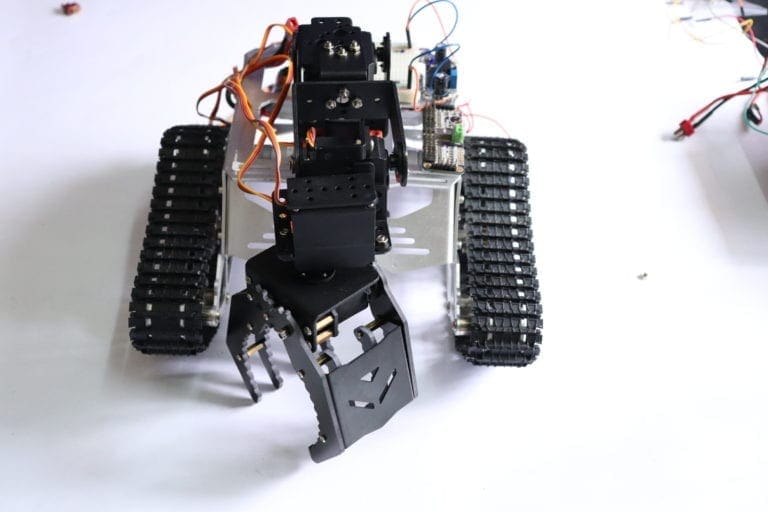
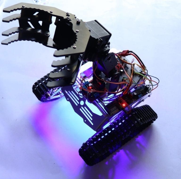
- A Robot chassis
- 9 Volt battery
- Smartphone / Alexa
For this project, I will be going with Arduino Nano 33 IoT.
Voice Controlled Car using Arduino – Step by Step Instructions
Step 1 – Circuit
First, we will take a look at the circuit. This is the circuit. You can try it out on a breadboard and once you are done, you can use it as such for the project or make your own PCB. I personally like PCBs. PCBs are neat and help to get rid of all nasty wires hanging around. And it’s cool to make your own PCBs for your project right?
Drawing Schematics and PCB Design using Altium

So I used Altium Designer to draw the circuit and design the PCB. It is a powerful tool that can be used to design and create your own PCBs for your project as well as complex and multiplayer PCBs for industrial use. Here is the link to the Altium trial version.
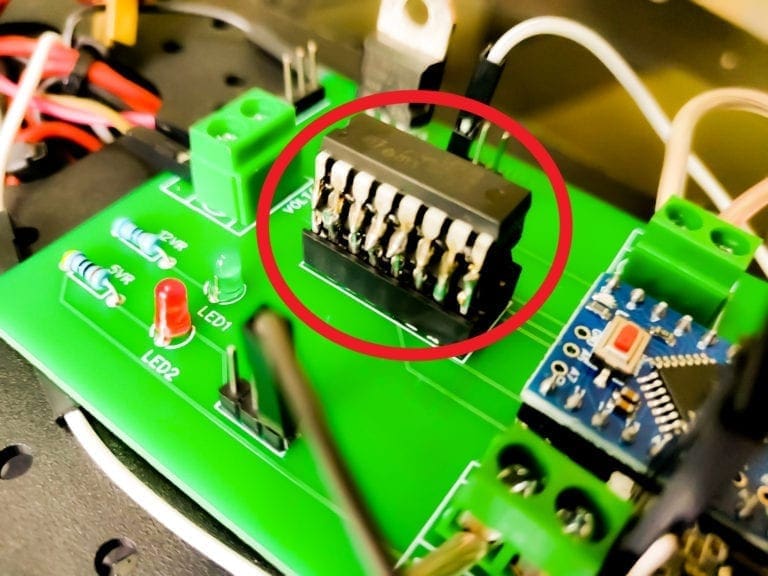
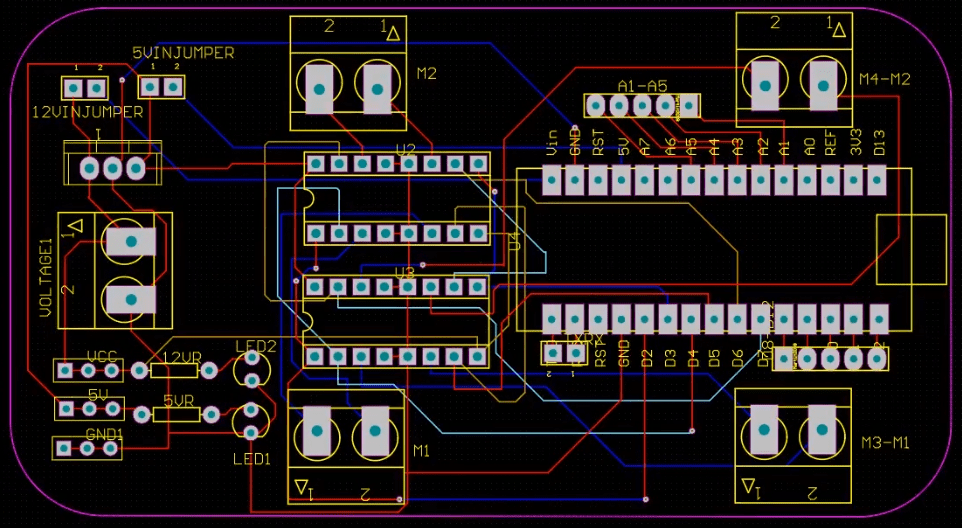
Here, I have designed a PCB layout where you can easily mount your Arduino Nano 33 IOT , L293D ICs and the supporting components and set this up without using messy wires and cables hanging around. The board is lightweight and can be powered using a 9V battery or a 9-12 V power adapter.


We need to power up the whole circuit and drive all 4 motors using L293D/L298N motor driver and our Arduino board. We need a powerful source that can provide enough current. So, I decided to go with a 12V LiPo battery.
The input power is connected to a 7805 regulator. 7805 is a 5V regulator that will convert an input voltage of 7- 32V to a steady 5V DC supply. There are indicator LEDs across various points for easy troubleshooting. You can either power your Arduino using 12V or regulated 5V output from the 7805 regulators. You can select that using a jumper.
Powering Arduino depends upon the type of board you are using. Here I am using an Arduino Nano 33 IOT which can withstand a voltage of 12V in its Vin pin. It’s not the case with all the boards. If I am connecting this 12 V directly, it may fry the chip. So, If you want, you can use a voltage regulator to step down the voltage to 5V before feeding it to Arduino. Now let’s take a look at the software part

Step 2 – Arduino IoT Cloud
Here I’ll be coding Arduino Nano 33 IoT, using Arduino IoT cloud. First, we will log in to the console and go to the device tab. Here you can see Arduino Nano 33 IoT board has been already added to the device list. This was shown in the previous videos. If you have any doubts regarding this don’t worry guys we have a tutorial specially for that. You can simply click on this link and watch that first.
Step 3 – Creating a New Thing for Voice Controlled Car
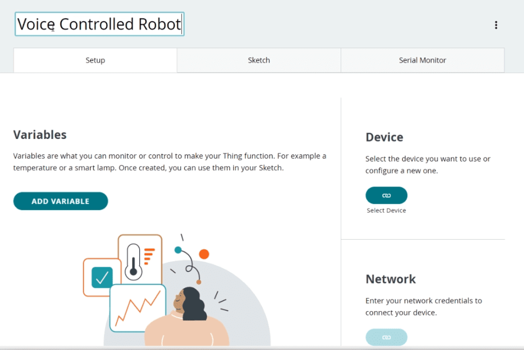
Once we have completed setting up our board, we will create a new project in Arduino IoT Cloud. Go to things and click on ‘create thing’. This is the page where you will be able to see complete details about your project. Here you will see complete details about your project like the board attached, variables, network, sketch, etc. First, we will give our project a name; say Voice Controlled Robot.

Step 4 – Add Variables for Controlling Robot
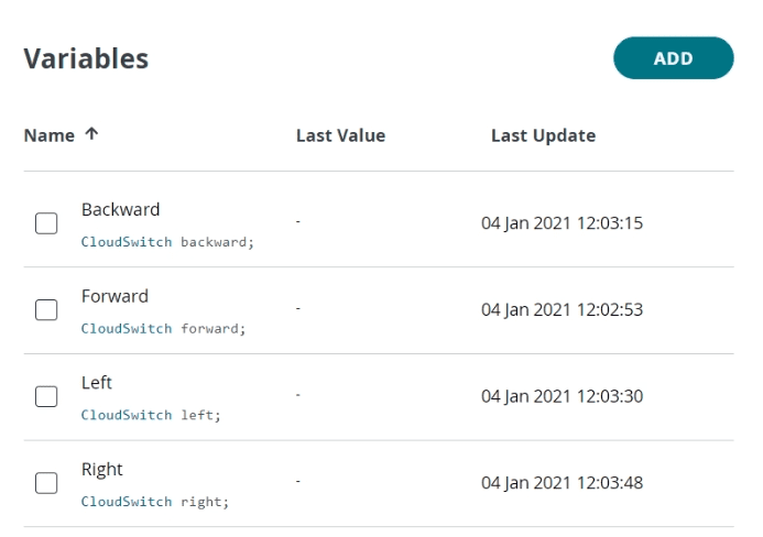
Next, we will add 4 boolean variables to control the direction of the Robot.

Step 5 – Creating Dashboard
Next, we will create a dashboard and add 4 buttons that will enable us to control the 4 variables from the dashboard. Once we create these widgets, we will link them to the corresponding variables.
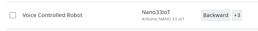
Step 6 – Attaching Board to
Next, we will attach this project to the board Arduino Nano 33 IoT.

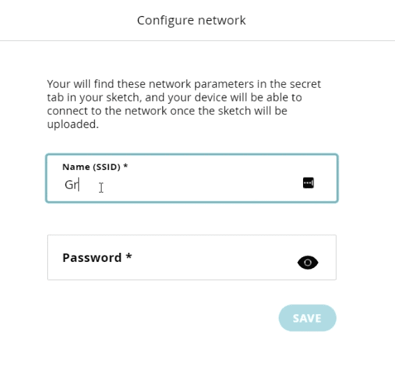
Step 7 -Setting up Network
Now, we will configure the network connection. For that, you can use the configure button under the network. Here, you should provide the WiFi name and password.

Step 8 -Code for Voice Controlled Car using Arduino
The advantage of using Arduino IoT cloud is once you have set up your thing and all the variables it will automatically generate a skeleton code which will include all the variables and critical function which is required to run the code. We just have to add extra variables and functions. So guys this is the skeleton code. Now I will be removing all unnecessary comments so that it will look, neet. And here is our final code guys now let’s take a deeper look into it.
The Code
#include "thingProperties.h"

void setup() {
  Serial.begin(9600);
  delay(1500);
  initProperties();
  ArduinoCloud.begin(ArduinoIoTPreferredConnection);
  setDebugMessageLevel(2);
  ArduinoCloud.printDebugInfo();
}

void loop() {
  ArduinoCloud.update();

}

void onForwardChange()
{
  if (forward == true) {
  mforward();
  delay(1000);
  mstopp();
  forward==false;
  }
}


void onLeftChange()
{
  if (left == true) {
  mleft();
  delay(500);
  mstopp();
  left==false;
  }
}


void onRightChange()
{
  if (right == true) {
  mright();
  delay(500);
  mstopp();
  right==false;
  }
}


void onBackwardChange() {
  if (backward == true) {
  mbackward();
  delay(1000);
  mstopp();
  backward==false;
  }
}

void mforward()
{
  analogWrite(2, 155);
  analogWrite(3, 150);

  digitalWrite(5,LOW);
  digitalWrite(4,HIGH);
  digitalWrite(6,LOW);
  digitalWrite(7,HIGH);
}

void mbackward()
{
  analogWrite(2, 155);
  analogWrite(3, 150);

  digitalWrite(5,HIGH);
  digitalWrite(4,LOW);
  digitalWrite(6,HIGH);
  digitalWrite(7,LOW);
}

void mleft()
{
  analogWrite(2, 100);
  analogWrite(3, 180);

  digitalWrite(5,LOW);
  digitalWrite(4,HIGH);
  digitalWrite(6,LOW);
  digitalWrite(7,HIGH);
}
void mright()
{
  analogWrite(2, 150);
  analogWrite(3, 70);

  digitalWrite(5,LOW);
  digitalWrite(4,HIGH);
  digitalWrite(6,LOW);
  digitalWrite(7,HIGH);
}

void mstopp()
{
  analogWrite(2, 20);
  analogWrite(3, 254);

  digitalWrite(5,LOW);
  digitalWrite(4,LOW);
  digitalWrite(6,LOW);
  digitalWrite(7,LOW);
}
Code Exlpained
Code is pretty simple. First, we are adding everything that is needed for the project like the libraries and the variables.
In the setup function, we will initialize the serial communication, communication with Arduino cloud, and then prepare the carrier to run the remaining code.
These are the four functions that will run when there is any change in the corresponding variables.
And these are the functions that will move the robot. I hope you guys are familiar with driving motors using motor driver IC. If you are not, check out our previous videos where we explain different motor driver IC from scratch.
When one of the values changes, the corresponding function will run. For example, when the forward variable changes, the mforward function will run. Your code is finished and you can upload your code to ou board.
Now, how do we change the variable? That’s right, we will toggle the switch using Alexa.
Step 9 -Controlling Robot using Alexa Voice Commands
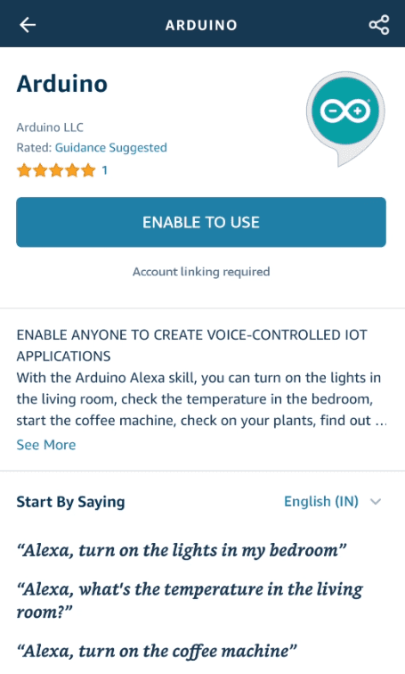
Now, take out your smartphone and launch Alexa App. Go ahead and install the Arduino Skill for Alexa and login with your credentials.

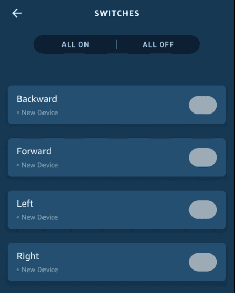
Now tap on discover devices. It will start scanning for any IoT based Alexa supported devices. Once the scan is completed, it will show you all the variables we created earlier. Setup those devices and click done.

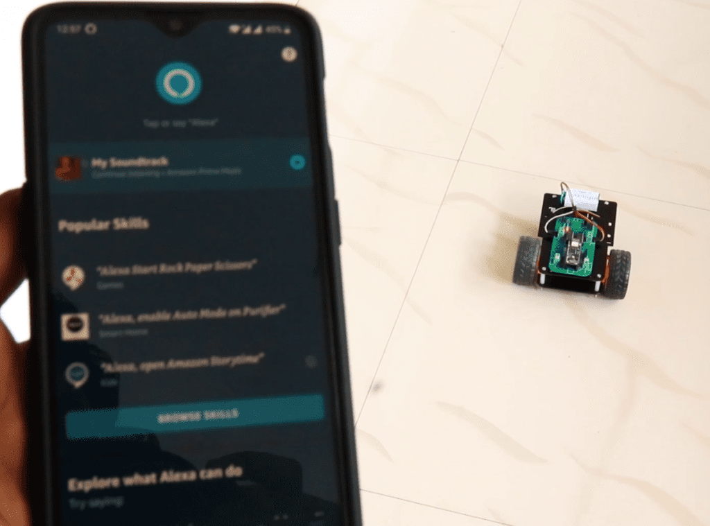
Lets Roll!
That’s it, guys. You should now be able to control the Robot using your voice command.

If you like this project and really interested in building amazing DIY projects make sure you subscribe to our channel by hitting the subscribe button here. Now, let’s get started with the project.