Automatic Plant Watering System using Scheduler and Arduino IoT Cloud
Introduction
Using a scheduler in your DIY electronic projects is like having a helpful assistant for your gadgets and devices. It’s a clever way to make your creations do things automatically at specific times or under certain conditions. With a scheduler, you can tell your project when to turn on or off, remind you of important tasks, or even make it work smarter.
In this video, I will be showing you how you can integrate Scheduler with Arduino and make your own projects to schedule different events to happen at specific times.
Arduino Nano ESP32
For this project, we are using the latest version of Arduino Nano Board – The Arduino Nano Esp 32. With its inbuilt Wireless chipset, it makes it easier to connect your projects to the internet, allowing you to control and monitor them remotely using a smartphone or computer.
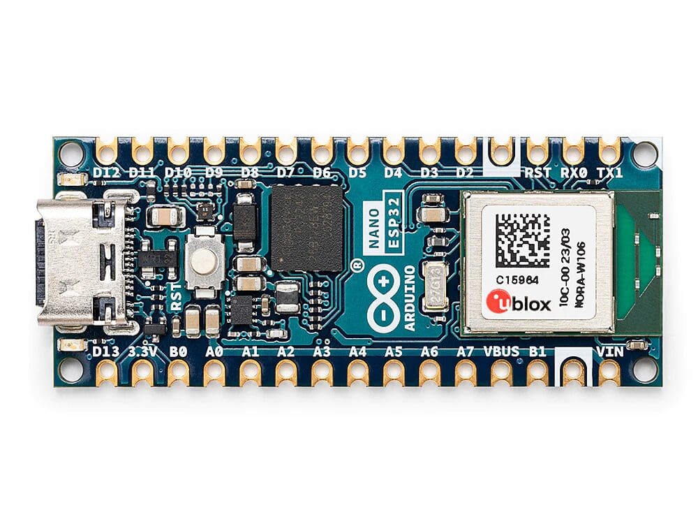
This means you can turn lights on and off, check the temperature, or receive notifications from anywhere. Second, the Arduino Nano’s compact size makes it suitable for smaller projects where space is limited.
Arduino IoT Cloud
Also, we will be making use of the Arduino IoT cloud in order to set up the project. If you haven’t tried the Arduino IoT cloud yet, I strongly recommend you to give it a shot.
Arduino IoT cloud lets you easily connect your gadgets to the internet, so you can control them from anywhere with an internet connection.
The Scheduler
Recently, a new feature was developed for the Arduino IoT cloud that will take our DIY skills to a whole new level. The scheduler feature of the Arduino IoT Cloud is like having a helpful assistant for your DIY electronic projects. It lets you plan when your devices should do specific tasks automatically. For example, you can set it up to turn on lights at a certain time or measure the temperature regularly and send you updates.
Circuit
Now we are going to make a circuit in which we can connect simple electronic devices that can be used with the scheduler.
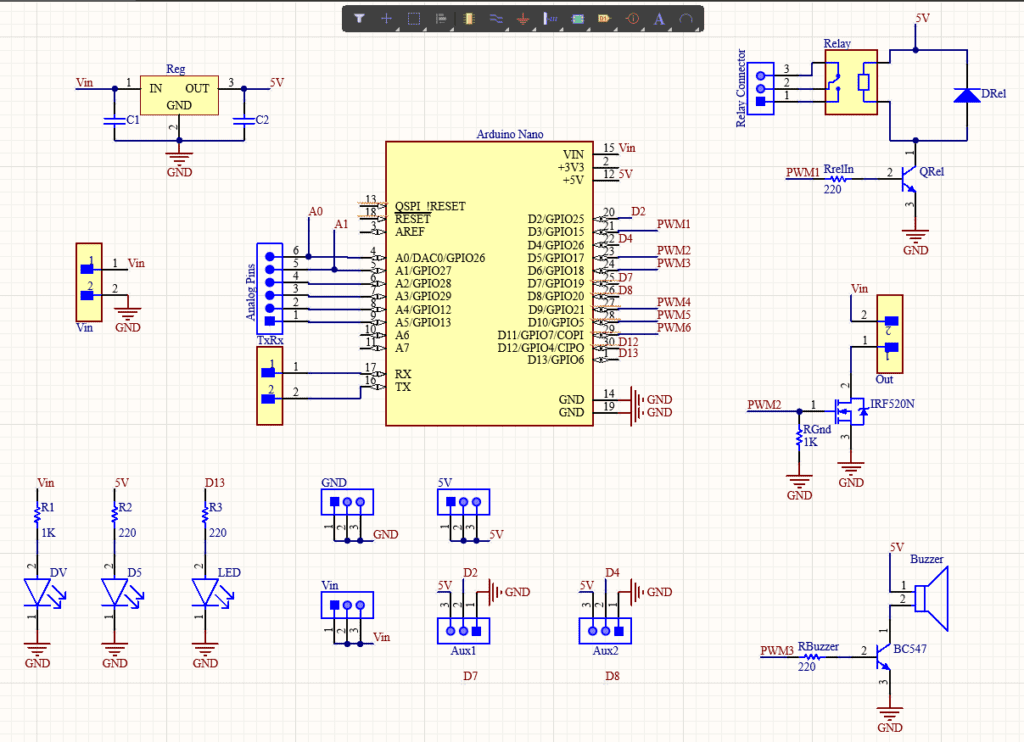
So let’s start with the circuit! I used Altium Designer to draw the circuit and design the PCB. Here we are in Altium Designer. Here I will be using a pump that works on 12 V, so I will be connecting a 12 V DC adapter. The input power is connected to a 7805 regulator. 7805 is a 5V regulator which will convert an input voltage of 7- 32V to a steady 5V DC supply. There are indicator LEDs across various points for easy troubleshooting.
Here, there are 2 switches. One is a Relay that is turned on by a transistor BC547, whose base is connected to Digital Pin 3. And then there is a MOSFET that is connected to the digital Pin 5 of the Arduino. Here you should also see a buzzer that is turned on and off by this transistor right here. This transistor is connected to digital pin 6 of the Arduino.
You can either connect the lock to the MOSFET or the Relay which can be turned on and off programmatically. I decided to connect the pump to the MOSFET so that I could connect some other device like a bulb or something to the relay. You can use the other switch to connect to any additional devices like a lamp or a motor to open the door or light the lamp with the scheduler.
This is just my design, Like I said earlier, I will provide the schematics in the description so that you can redesign the entire thing, customize it, and then make your own version of it. Or you can make my version as such. Whatever you do, the first thing is to try it out on a breadboard. Once you get the output, then you can use it as such or make your PCB.
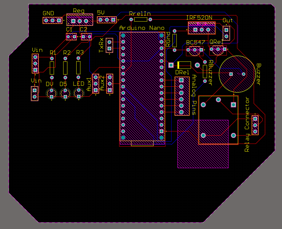
I decided to go with the PCB. I have designed a PCB layout where you can easily mount your Arduino Nano ESP32, relays, MOSFETs, and other components, set this up without using messy wires and cables hanging around. And it’s cool to make your own PCBs for your project right? The board is lightweight and can be powered using a 9V battery or a 9-12 V power adapter depending on the Solenoid Lock voltage.
PCB
I ordered PCB from PCBWay. PCBWay is a PCB manufacturer specializing in PCB prototyping, low-volume production, and neat and tidy PCB assembly. If you are interested in making your own PCBs for your project, check out the link below. You can get a 5-dollar discount when you sign up using the link below and get an additional 5-dollar discount at the checkout by providing the coupon code PCBWayLab.
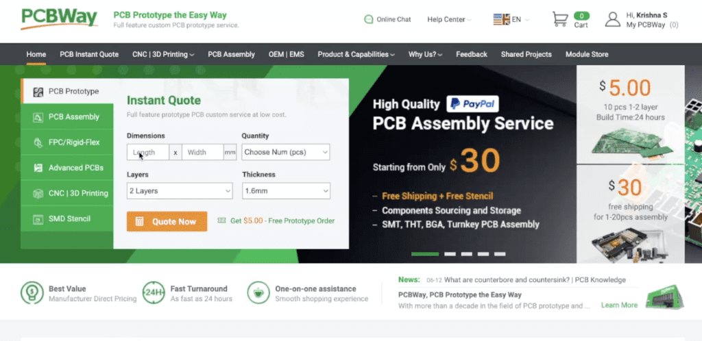
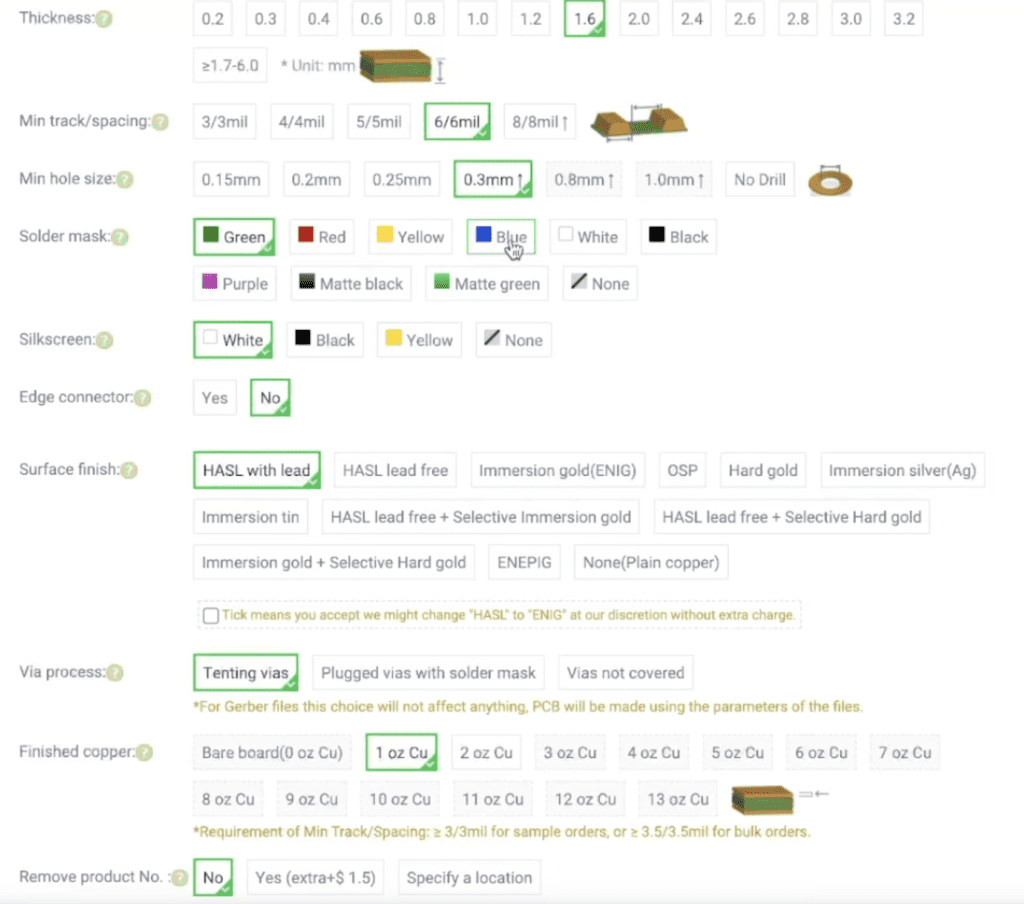
To order your PCB from PCBWay, go to the PCBWay website and fill in the basic board details in the instant order form. From there you will be directed to a form where you can provide more elaborate board details. Update your board information in the PCB specification screen. On the next screen, you should be able to upload your Gerber file and submit it for review. Once the review is completed, all that is left is to add to the cart, make payment, and wait for your PCBs to arrive.
Once you get all the components and the PCB, it’s time for you to solder them together. Solder all the components onto the board and make sure to check the polarity of the components. After soldering the PCB looks like this.

Arduino IoT Cloud Setup
Now we can go to Arduino IOT Cloud and log in with your credentials. This is the project that we are working on. Now if you go inside this, we will be able to see everything that is linked to this project.
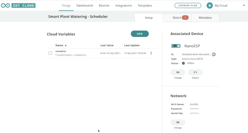
Here you can see all the variables, that are linked to this project, currently, we only have one which is this cloud scheduler variable named scheduler.
Also, we can see that this project is linked to the board Arduino Nano ESP 32. If you wanna know more about Arduino IOT Cloud make sure to check my previous video where I explain everything you need to know to get started with Arduino IoT Cloud! And I have configured my network here.
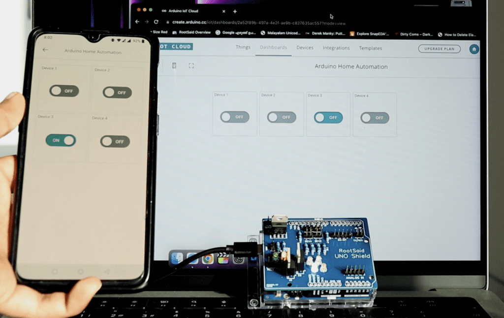
Now I wanna show you one more thing, before we start coding, let’s go to the dashboard and open this one. This is a scheduler widget. This is where we configure when the scheduler should be active and when it should not.
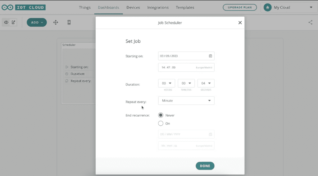
Here I have configured to run 4 seconds of every minute. Now let’s start coding. This widget is linked to the scheduler variable I showed you earlier.
Code
Now let’s go to sketch.
If you take a look at the code here we can see that the variable has already been declared so we don’t have to declare it once again. Here in the setup function, we are initializing the serial communication and we are setting the pin mode of these pins as output. These pins are connected to MOSFET, relay, and LED and the MOSFET can be used to control the device.
Once that is done the Arduino board will be connected to the Wi-Fi network that we configured earlier and here in the loop function we can see that this function will be checking for any changes in the variable scheduler that we created earlier.
And inside this if condition, we tell it what to do. So in this case, when the scheduler is ON, turn ON these pins and when the scheduler is not activated we should Turn off these pins.
Now all you have to do is compile and upload the code.
Testing
Now you can first check with a timer and a multi-meter and see if the pin is properly triggered at the right time.
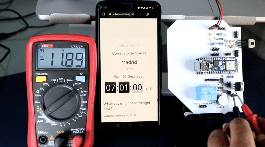
Once everything is done, connect everything together. Connect the input valve of the pump tp a water source and the other end to a plant pot. Now, just to show you how the scheduler works, I will put this mobile phone showing this time here.
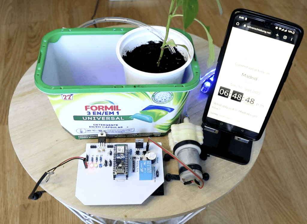
Now exactly when the time next minute starts, this pump will turn on for the next 4 seconds and turn off.
This is just a demo. There are a lot of things you can do with it. It all depends on your creativity.
So if you have any doubts, please feel free to ask in the comment.