Building a Home Automation using Arduino and Arduino IOT Cloud | Arduino IOT Projects
Building an Arduino Smart Home Introduction
Welcome to the beginner’s tutorial on building your very own home automation system using an Arduino Board, Arduino IoT Cloud, and control everything with your mobile phone! Home automation is an exciting and innovative way to control various devices in your home, making your life easier and more convenient.
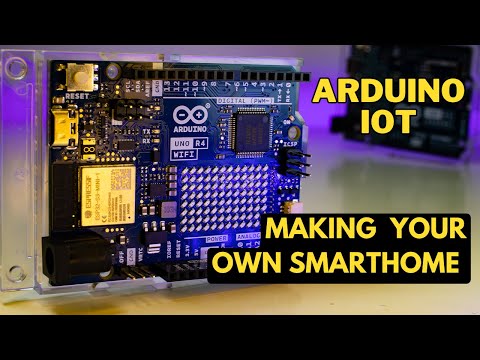
In this step-by-step guide, we will walk you through the process of setting up and configuring an Arduino-based system that allows you to monitor and control devices remotely using the power of the internet and your smartphone. So, let’s dive in and embark on this journey to create a smart and interconnected home of the future!
Building the Smart Home Components Needed
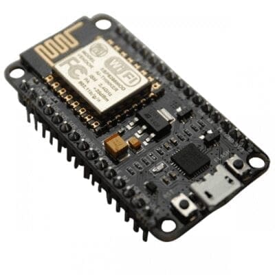
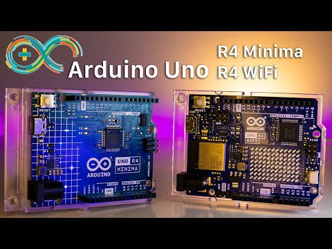
The first you will need is an Arduino Board with Wireless connectivity. Here for this project, I will be using Arduino UNO R4 WiFi. Powered by a Renesas RA4M1 32-bit Cortex®-M4 CPU, this enhanced iteration of the renowned Arduino UNO board. This is the latest iteration Arduino UNO board with a lot of new features like wireless connectivity, USB type C connector, 5V operating voltage, and backward compatibility with most of the older sensors and libraries. If you wanna know more about it, check out our previous video where we explain everything about Arduino.
Then we will need some resistors, some LEDs, MOSFETs, and some connecting wires. Then we will need a breadboard to test the whole thing.
Smart Home Circuit
let’s take a look at the circuit as well as the component. Here we have the Arduino, some MOSFETs 7805 voltage regulators some LEDs, and some header pins. We have a header pin where we’ll be connecting the voltage input. This voltage input can be a 9-volt battery or a 12-volt DC adapter. This voltage input will be connected to a 7805 voltage regulator where this Vin will be converted to a steady 5V DC Supply, which can be connected to multiple devices
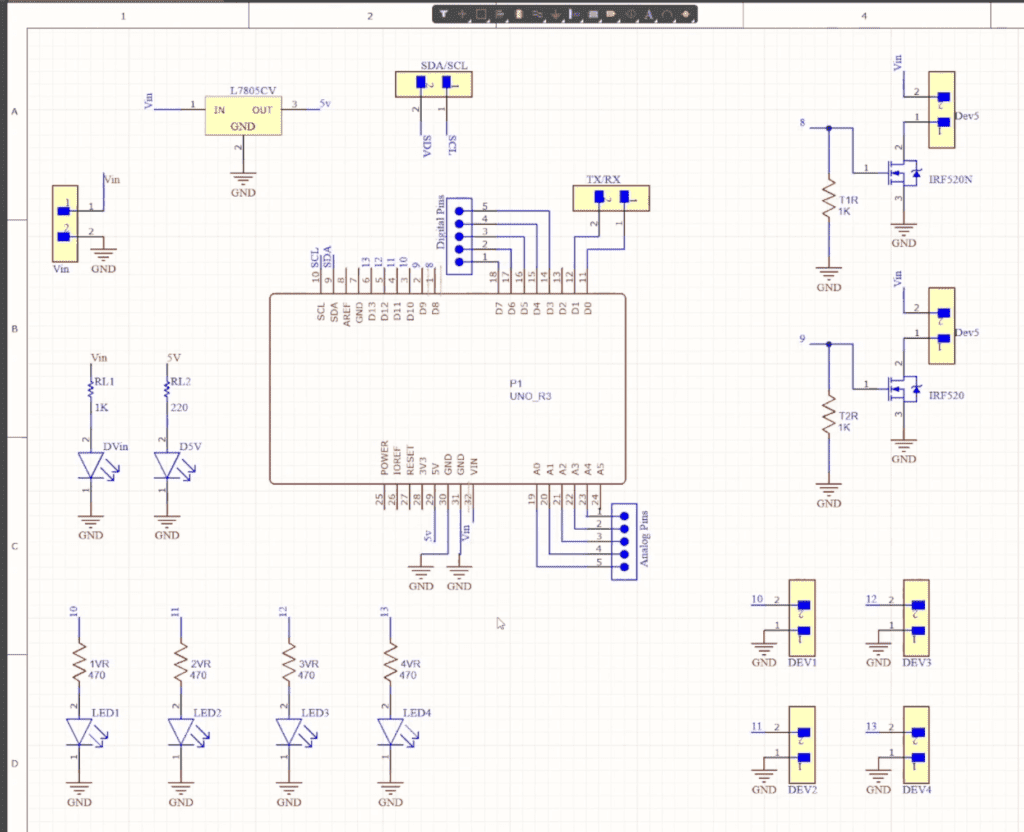
Also, you should be able to see two MOSFETs configured as switches and these are connected to pin 8 and pin 9 of Arduino. That means using pin 8 and pin 9 we will be able to turn on and off these MOSFETs. There are two terminal blocks connected to each MOSFETs where electronic devices can be connected. So basically when these MOSFETs are turned on, this circuit will be completed and the device connected to this terminal block will be turned on and vice versa.
Then there are some more terminal blocks connected to pins 10, 11, 12, as well as 13 of Arduino. Here you should be able to connect any device with an operating voltage of 5V. Also if you want, you can connect a 5-volt relay at these points and you can play around with AC devices as well.
The best thing about this Arduino board is its operating voltage is 5 volts which means all the sensors that we could use with the previous version of this board can also be used with this board as well so if you want to connect any external sensors or modules you can use these header pins.
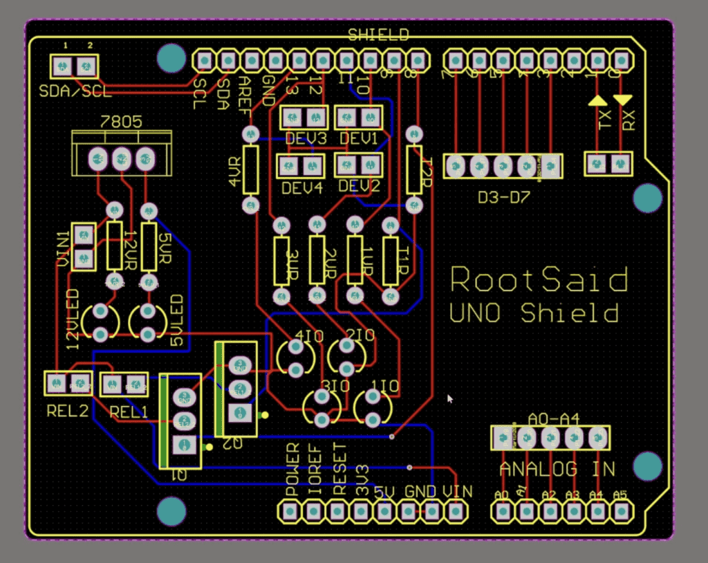
Once the circuit was finished and tested, I designed a compact PCB using Altium, where I can fix all the components neatly. Here you can see routing is on both sides of the board which means it is a dual-layer PCB. Altium PCB Designer’s interactive routing techniques enable us to route tracks in PCBs more quickly than ever before!
Getting the PCBs Done
I ordered by PCB from PCBWay. PCBWay is a PCB manufacturer specializing in PCB prototyping, low-volume production, and neat and tidy PCB Assembly. To order your PCB from PCB Way, go to the PCBWay website and fill in the basic board details in the instant order form.

From there you will be directed to a form where you can provide more elaborate board details. Update your board information in the PCB Specification screen.
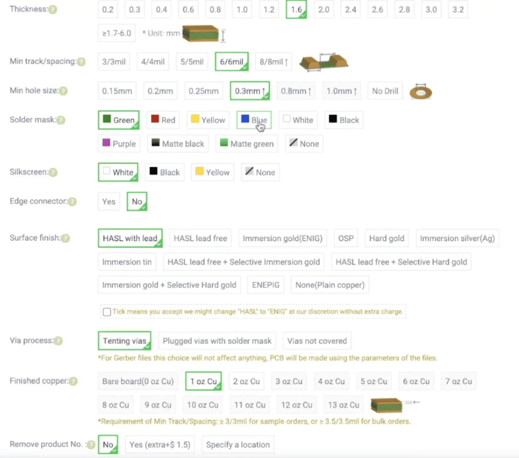
In the next screen, you should be able to upload your Gerber file and submit it for review. Once the review is completed, all that is left is to add to the cart, make payment, and wait for your PCBs to arrive.
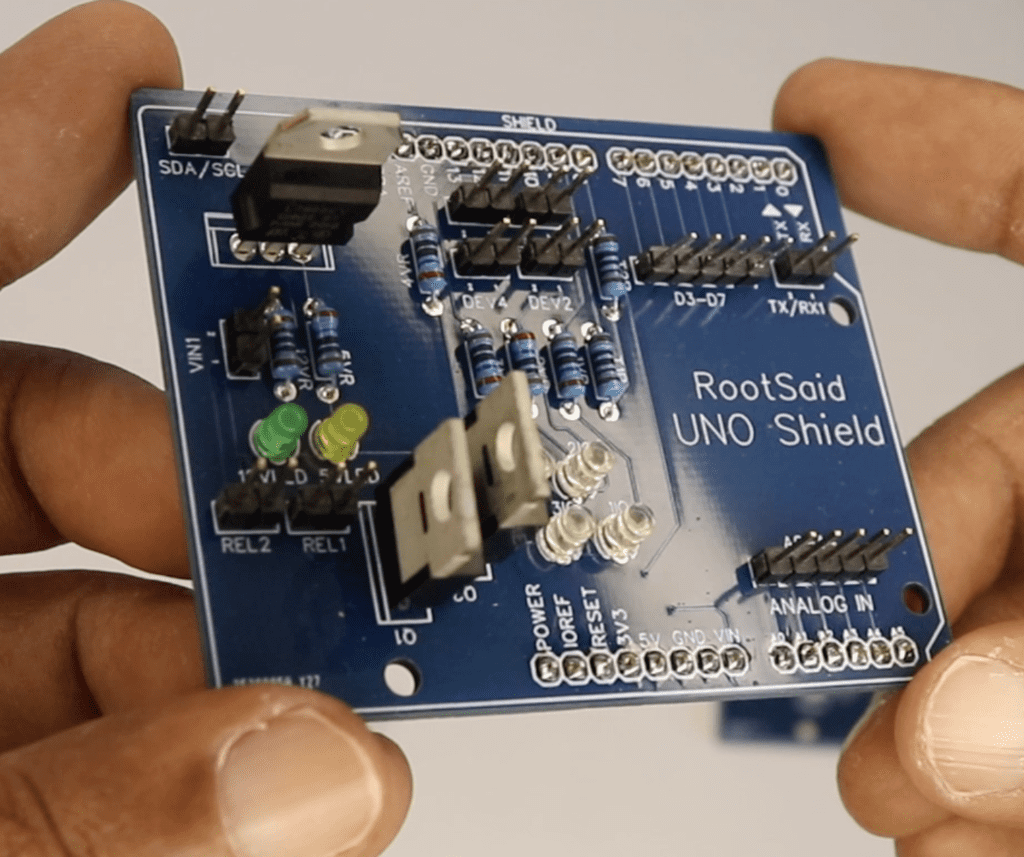
Once you get all the components and the PCB, it’s time for you to solder them together. Solder all the components onto the board and make sure to check the polarity of the components. After soldering the PCB looks like this.
Now, let’s get down to the software part. Here, I will be programming the board using Arduino IoT Cloud.
Configuring the Smart Home in Arduino IOT Cloud
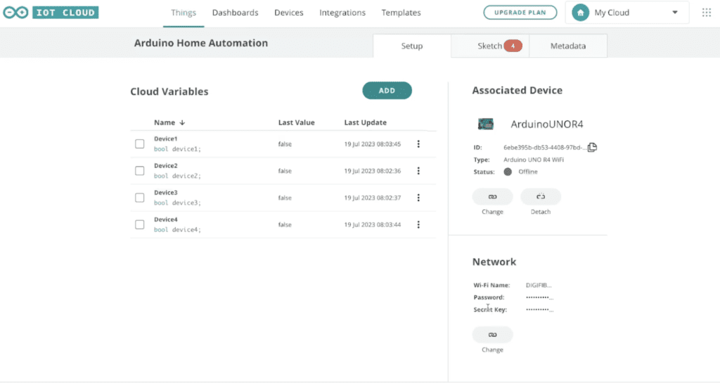
Now let’s go to Arduino IOT Cloud and sign in with your username and password. Under the things you should be able to see all the projects that you have worked on that are currently linked with Arduino IOT Cloud. This Arduino Home Automation is basically the thing that I have configured for this project.
There we should be able to see all the properties that are related to this project. Here you can see we have four Cloud variables – device1, device2, device3, and device 4. This project is associated with the Arduino Uno R4 that we added earlier.
If you don’t know how to program your Arduino board using Arduino IOT Cloud and control it using the browser, please do check out the video that I uploaded earlier where I explained everything you need to know about programming an Arduino board and controlling it using Arduino IOT Cloud. So watch the video below and continue,
Here I have also configured the network details as well. The reason why I created four variables is to control four devices. Let’s go to the dashboard and here you should be able to see four buttons.
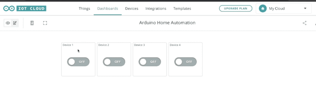
Now so these four buttons are linked to the four variables that I showed you earlier. That means if I turn on this switch the value of the device one variable will be changed to True likewise if I turn off the switch the value of the device one variable will be changed to False. Now go back to things and let’s take a look at the code and click on the sketch.
The Code
If you take a look at the code here we can see that these four variables have already been declared, so we don’t have to declare it once again. Here in the setup function, we are initializing the serial communication and we are setting the PinMode of 10, 11, 12, and 30 as output pins. So basically these four pins are connected to four LEDs, which are connected to the header pins. Once that is done the Arduino board will be connected to the Wi-Fi network that we configured earlier.
In the loop function, we can see that this function will be checking for any changes in the variables that we created earlier that is device one device two device three, and device 4. So if there is any change in the value of this variable device1 then the function onDevice1Change() will be executed. Likewise, if there is any change in the value of the variable device2 then the function onDevice2Change() will be executed.
So what exactly this function doing is, if the value of device1 is changed to TRUE then the pin 10 will be switched to high. That means it will be turning on the LED that is connected to pin 10 and if not if the value is FALSE, that means it will be turning off that LED. So this is the same for all four variables. Now all you have to do is connect your Arduino board to your computer and upload this code to your board.
Testing
Once the code is uploaded, check out the serial monitor and make sure this board is getting connected to Arduino IOT Cloud properly if it is getting connected, go to the dashboard and try to turn On and Off the switches one by one. You should be able to control all four LEDs one by one using the dashboard in your Arduino IOT Cloud.
You can do the same thing using your mobile phone as well.
All you need to do is install the Arduino IOT Cloud application on your mobile phone connect to your account and open the dashboard and try tapping on the buttons one by one.