Love is In the Circuit! Beating Heart PCB for Valentines Day
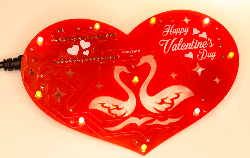
Hey guys it’s valentine’s day! So let me ask you a question. what gift are you going to give to your valentine? Me? Well, I decided to make something different. This time, I decided to go with this Heart Shaped DIY PCB. Love is in the Circuit. Today, I am going to show you how you can make this Heart shaped PCB within minutes.

Well, that looks a bit hard right, All the drawings and all. Well, the best part is, you don’t even have to know how to draw. I will be giving you all details including the circuit diagram, the drawing, and complete codes and instructions to make your own. I will also share the link to the Gerber file and you can download it if you want. So let’s get started.
I used an Altium designer to draw the circuit and design the PCB. It is a powerful tool that can be used to design and create your own PCBs for your project as well as complex and multiplayer PCBs for industrial use. I will leave the link to the free trial version in the description.
The Circuit
Here we are in Altium designer. Input voltage is connected to the Vin pin of Arduino. The ground pin is connected to the ground pin of Arduino. Digital Pins from 2 to 11 are connected to LEDs via resistors.

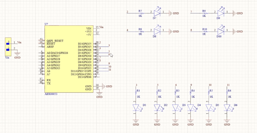
Pin numbers 3,5,6, 9, 10, and 11 are PWM pins using which we will be able to fade in and fade out the LEDs which will create a heartbeat effect. All other pins – 2, 4, 7, and 8 are Digital Pins that will be on all the time.
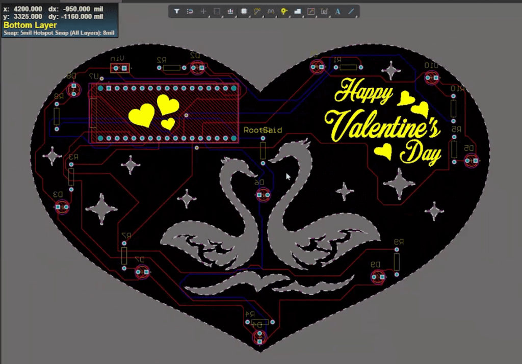
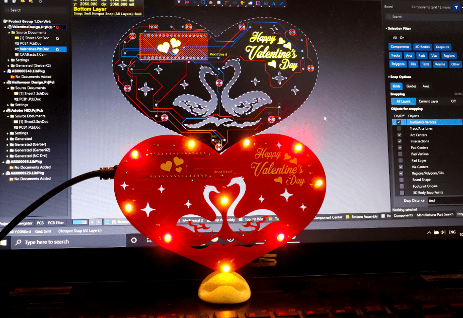
The next step is where we deviate from all the previous projects. Here we will be designing a Heart-shaped PCB where we can securely solder the Arduino, the header pins, transistors, resistors as well as LEDs.
Designing the Heartshaped PCB
The first thing we need is the shape of a Heart. For that, you can draw a heart using these tools or you can import a heart shape saved as a DXF file. For this project, I decided to go with the second option. I will leave the link to this DXF file in the description.

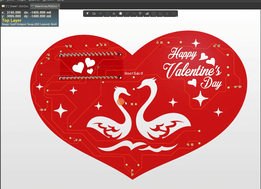
To import the heart go to files import and select DXF/DWG file. Browse the file and hit open. If you want you can resize the heart to fit all the components. Once the heart is in the right size, we can define the boat shape using this drawing. For that go to design, board shape, and define board shape from selected objects. And there we go. The board shape has been designed. Now you can arrange all the components inside this heart and once you have arranged all the components you can route it and export the Gerber files.

Getting the PCB Done!
I ordered PCB from PCBWay. PCBWay is a PCB manufacturer specializing in PCB prototyping, low-volume production, and neat and tidy PCB assembly and you can create a variety of PCBs with different specifications. We will look into it in a second.


To order your PCB from PCBWay, go to the PCBWay website and fill in the basic board details in the instant order form. From there you will be directed to a form where you can provide more elaborate board details. Update your board information in the PCB specification screen.
Now update the board information in the PCB specification screen. I want to give the red color to these PCBs, so I chose the red color for the solder mask.
In PCBWay, we can select a variety of color PCBs such as purple, black, orange, and even create transparent PCBs by selecting a transparent solder mask.
Also, I chose a white silkscreen instead of black. Perfect. On the next screen, we should be able to upload the Gerber file and submit it for review. Once the review is completed, all that is left is to add to the cart, make payment, and wait for the PCBs to arrive.


Coding
void setup() {
pinMode(2, OUTPUT);
pinMode(3, OUTPUT);
pinMode(4, OUTPUT);
pinMode(5, OUTPUT);
pinMode(6, OUTPUT);
pinMode(7, OUTPUT);
pinMode(8, OUTPUT);
pinMode(9, OUTPUT);
pinMode(10, OUTPUT);
pinMode(11, OUTPUT);
}
void loop() {
  analogWrite(2, 255);
  analogWrite(4, 255);
  analogWrite(7, 255);
  analogWrite(8, 255);


  for (int i = 0; i < 255; i = i + 7) {
    analogWrite(11, i);
    analogWrite(3, i);
    analogWrite(5, i);
    analogWrite(6, i);
    analogWrite(9, i);
    analogWrite(10, i);
    delay(5);
  }
  for (int i = 255; i > 0; i = i - 7) {
    analogWrite(3, i);
    analogWrite(5, i);
    analogWrite(6, i);
    analogWrite(9, i);
    analogWrite(10, i);
    analogWrite(11, i);
    delay(5);
  }
  delay(200);
  for (int i = 0; i < 255; i = i + 7) {
    analogWrite(11, i);
    analogWrite(3, i);
    analogWrite(5, i);
    analogWrite(6, i);
    analogWrite(9, i);
    analogWrite(10, i);
    delay(5);
  }
  for (int i = 255; i > 0; i = i - 7) {
    analogWrite(3, i);
    analogWrite(5, i);
    analogWrite(6, i);
    analogWrite(9, i);
    analogWrite(10, i);
    analogWrite(11, i);
    delay(5);
  }
  delay(400);

}
Testing
Awesome right? Now all you have to do is program our Arduino. I will provide the link to the code in the description.


So here we go, guys. Beating Heart PCBs. We hope you’ve enjoyed our Beating heart project.