
Long Range Remote Controller for RC Robot | DIY Remote Controller using HC12
Hey, guys welcome back. In this post, I will be showing you how to make a long range remote controller for your robot. Yes, a Cheap DIY Remote Controller for your Robot using HC12 module. Here I will be giving you complete details including the circuit diagram the PCB layout and video tutorial and complete details to build your own remote controller for your robot.
How to make a Long Range Remote Controller for your RC Robot?
Components Needed
First we will take a look at the components needed to make your DIY Remote Controller for RC robot.
- Breadboard – Get it Now
- Arduino joystick – Get it Now
- Accelerometer – Get it Now
- Push button – Get it Now
- LED – Get it Now
- Jumper wires – Get it Now
- Arduino Nano – Get it Now
- HC12 wireless module – Get it Now
Getting Started with Robotics?
Want to learn Robotics from Scratch? Here is an awesome guide for you to get started with robotics (Free Video Tutorials Included).
Parts of a Remote Controller
We will divide our long range remote controller into 3 parts
- Input
- Processor
- Transmitter
Input is the unit using which the remote controller gets data from the user. For example Joystick, Accelerometer, buttons, potentiometer etc. For this project, we will be using Accelerometer, Joystick and push buttons.
The Processor is the part that reads the data from the input unit, process/condition them for the Transmitting unit to send. Here we will be using Arduino Nano to process input.
The Transmitter is the part that sends the data from the remote controller to the robot’s receiving unit wirelessly. For our project, we will be using the HC12 Wireless module.
HC12 Wireless Module for Cheap Remote Controllers
This is one of the most commonly used wireless modules in the field of robotics and other remote control applications. it is very easy to use and have a very long range communication; upto 1 KM LOS.

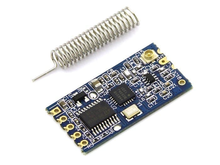
It is a 5 pin wireless module which can be very easily be connected to arduino Raspberry Pi or other microcontroller boards without causing any trouble. this wireless module works on 5 volt. so you won’t have to use any logic converters to use this wireless module with most of the arduino boards.
First, we will build the circuit in a breadboard. once we get everything right we will use that circuit to make our own PCB.
Why HC12 Module?
- Comparatively Cheap
- Easily Available
- Only needs 2 Pins for data transmission
- Long Range (Up to 1 KM with External Antenna)
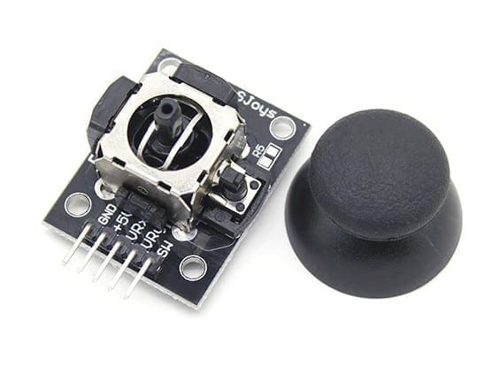
Joystick
This is one of the most commonly used analog joystick module which designed to work with Arduino. It has two analog potentiometers – one detect the vertical motion of the joystick and other detects the horizontal movement of joystick. This is really cheap and can be easily be used with various projects like RC car, video game joystick.
You can download sample sketch for testing the working of joystick from the below link.

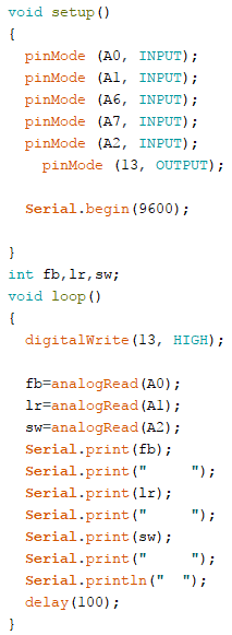
Before uploading the main long range remote controller code, make sure your joystick works by using this code. Download the code from the above link. In this example, what we are doing is simply collecting the data analog outputs from the Joystick using the analog pins (A0, A1, A2) of Arduino. These values are stored in the variables and are later printed on the serial monitor.
Making a Long Range Remote Controller
Remote Controller Prototype on Bread Board
Before going for the PCB it is a good idea to build the entire circuit on a breadboard. Building and troubleshooting electronics circuits in bread board is much easier as it does not require soldering. Once the final design is tested, we can create the PCB and solder it permanently.

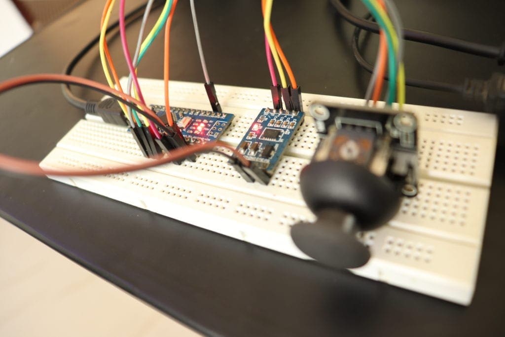
This is how I assemble all the components on the breadboard. Here I have an accelerometer add joystick Arduino Nano and wireless module HC12.
Remote Controller The connections (Bread Board)
Arduino – Accelerometer
- 5 Vout – VCC Arduino
- Gnd – Gnd
- X – A0
- Y – A1
Arduino – Joystick
- 5 Vout – VCC Arduino
- Gnd – Gnd
- X – A2
- Y – A3
- Switch – A4
Arduino – HC12
- 5 Vout – VCC Arduino
- Gnd – Gnd
- 10 – TX
- 11 – Rx
Long Range Remote Controller Arduino Code
Simply download the below code using the download link below and upload it to your controller.

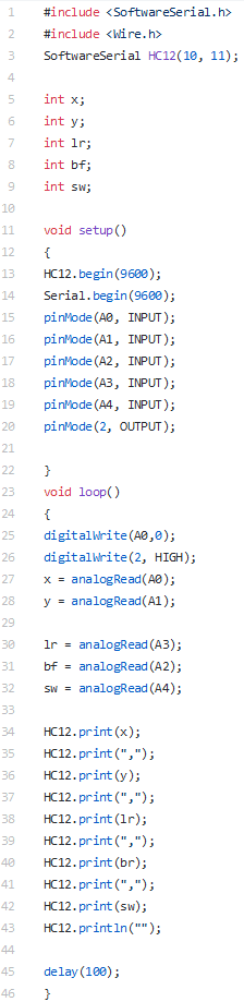
Code Explained
Basically, what this code does is, it will start a software serial connection at pin 10 and 11 (where we connect the Tx and Rx pins of HC12 wireless module). Arduino will read the analog voltage of the pins A0 – A4 where we connect the input units (accelerometer and joystick) and store their values in different variables. Then it will create a single long string by combining all the data which will then be send to the Remotely Controlled Robot.
Upload the code to the Arduino of the long range remote controller for your robot. Once it is done, open up the serial monitor. You will see all the sensor data that is being read by the Arduino as a Single line separated by commas ( , ). This is how our data will be sent to the Remote Robot.
Our breadboard assembled long range remote controller, using HC12 is now ready. Now we will receive these data using the HC12 receiver of the Robot.
Receiving the Data from the DIY Remote Controller
Now its time to receive the data from the remote controller. In the receiving unit (Robot), I used Arduino nano clone which.
First we read the data coming from the receiving module to a variable named ‘input’.
 include <SoftwareSerial.h>
 String input;
 int x,sx;
 int y,sy;
 int lr;
 int bf;
 int sw;
 String input;
 int boundLow;
 int boundHigh;
 const char delimiter = ',';
 SoftwareSerial hc12(4, 5);
 void setup()
 {
 Serial.begin(9600);
 hc12.begin(9600);
 delay(2000);
 }
 void loop()
 {
 if(HC12.available())
   {
   input = HC12.readStringUntil('\n');
   if (input.length() > 0)
       {
        Serial.println(input);

       boundLow = input.indexOf(delimiter);
       x = input.substring(0, boundLow).toInt();

       boundHigh = input.indexOf(delimiter, boundLow+1);
       y = input.substring(boundLow+1, boundHigh).toInt();

       boundLow = input.indexOf(delimiter, boundHigh+1);
       lr = input.substring(boundHigh+1, boundLow).toInt();

       boundHigh = input.indexOf(delimiter, boundLow+1);
       bf = input.substring(boundLow+1, boundHigh).toInt();

       sw = input.substring(boundHigh+1).toInt();

       delay(10);
 }
 }
 }
This ‘input’ is a long string of decimal numbers separated by commas. This string is broken down into smaller numbers and is then stored in separate variables.
You can now use these variables to drive your robot the way you want.
RC Pick and Place Remote Controlled Robot using Arduino
Now how about building a robot using this remote controller? Check this Out!!

Want to Build one?? Here is the Tutorial. Check the Link Below.
Hall Effect Sensor Gesture Controlled Glove
This is just a beginning. We, the RootSaid group is working on a wireless control glove that can be used to control the whole robot, including the robotic arm. But there is something cool about this glove.
This glove can detect hand gestures WITHOUT Flex sensor. Yes you heard that right. Want to find out more? Be a part of RootSaid.

Subscribe RootSaid Website by simply entering your Email ID below. You will receive notification whenever the tutorial is available for you to tinker with.
[mc4wp_form id=”1842″]
Rate the Project
Did you find this useful? Help us to improve by rating this page.
[mc4wp_form id=”1842″][RICH_REVIEWS_FORM] [RICH_REVIEWS_SNIPPET stars_only=”true”]

hello, i want ask..
so we need 2 of HC-12 module, 1 for receiver (remote) and 1 for transmitter (robot) ?
sorry i am beginner
Yes Bro..
No Problem, you can ask anything.
If I wanted to use a 3 position switch (3xOn) what resistors do you recommend for the low/mid/high positions?
Hello! Sir
Can you provide details about receiver and circuit diagram for both transmitter and receiver
i think the circuit diagram transmitter and receiver isnt different, but the sketch is different
Can u make a video about the reciever aswell for the robot cars in the first picture?
dear sir,
can u help me ?
how can i send two or more analog data & received led on off by using hc 12 with arduino
please me codes
aslampcml@gmail.com