Opla IoT Kit Tutorial | Getting Started with Arduino IoT
Arduino Opla IoT Kit Tutorial
Welcome back to RootSaid, in the previous post about Arduino Opla IoT Kit, I showed you everything you need to know about the new IoT kit by Arduino. We unboxed it, explain all the components and features, and show you how you can activate 12 month subscription for the maker plan. In this Opla IoT Kit Tutorial, I will be showing you how you can get started with this kit. I will show you how you can set up the device, add this device to the IoT cloud, and upload your first code to your Opla kit.

Opla IoT Kit Video Tutorial
If you are a beginner and you are totally interested in building your own robots and electronics projects, then this channel is for you! I am super excited to teach you everything you need to know about what you need to know!

In future videos, we will be going through each and every sensor separately and will show you how to make different smart devices with this Opla kit. So make sure you subscribe to our channel by clicking the subscribe button here. Also if you find this video useful, consider supporting our channel by giving this video a like! I would really appreciate it.
Getting Started with Arduino IoT Kit
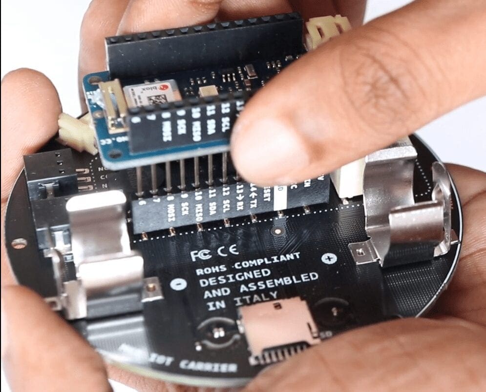
Connecting Carrier Board with Arduino MKR1010
To get started the first thing you need to do is connect the Arduino board to the carrier board. So do you in the previous video, all you have to do is just align the pins and simply press the board to the career. Simple as that.

Programming Opla IoT Kit
Now, you can use Offline Arduino IDE or Arduino IoT Cloud to program the Opla kit! In this video, I will be explaining both methods.
Coding Opla IoT Kit using Arduino IDE
First, we will take a look at offline method. For that, you will need the latest version of Arduino IDE. If you don’t have it you can download it from here.
Installing the Board and Library
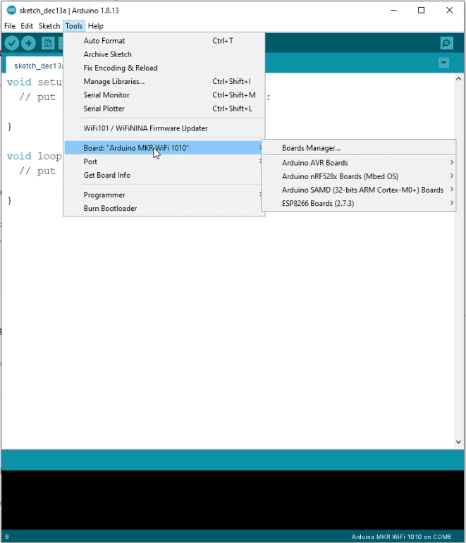
The first thing to check is whether the board is installed. If you are using the latest version of order no id you don’t have to worry about that. It should already be there. You should see that under Tools > Board > Arduino SAMD. If it’s not there you can easily install it using the board manager.

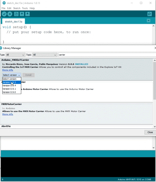
The next thing you need to do is install a library that will make it easier for us to communicate with the carrier board. The name of the library is “Arduino Maker IoT Carrier“. To do that all you have to do is go to the library manager and type carrier you should see Arduino maker IoT carrier. Select the latest version and click on install and that will set up the library.

Coding
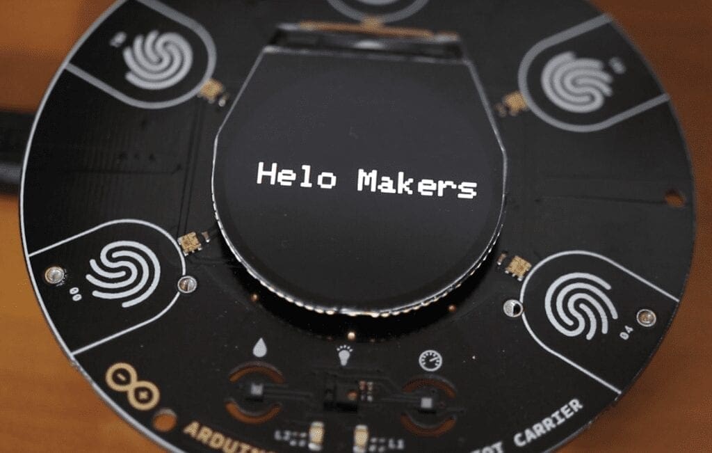
Now let’s upload the first program using Arduino IDE. This program is to read the temperature and humidity using the sensors which are inside the carrier board and display it on the led display when you press buttons.
#include <Arduino_MKRIoTCarrier.h>
MKRIoTCarrier carrier;
bool CARRIER_CASE = false;

float temperature = 0;
float humidity = 0;

void setup() {
  Serial.begin(9600);
  carrier.begin();
  carrier.display.setRotation(2);
}

void loop() {

  temperature = carrier.Env.readTemperature();
  humidity = carrier.Env.readHumidity();

  carrier.Buttons.update();

  Serial.print("Temperature = ");
  Serial.print(temperature);
  Serial.println(" °C");

  Serial.print("Humidity = ");
  Serial.print(humidity);
  Serial.println(" %");

  //function to print out values
  if (carrier.Button2.onTouchDown()) {
    printTemperature();
  }

  if (carrier.Button1.onTouchDown()) {
    printHumidity();
  }
}


void printTemperature() {
  carrier.display.fillScreen(ST77XX_RED); //red background
  carrier.display.setTextColor(ST77XX_WHITE); //white text
  carrier.display.setTextSize(2); //medium sized text

  carrier.display.setCursor(30, 110); //sets position for printing (x and y)
  carrier.display.print("Temp: ");
  carrier.display.print(temperature);
  carrier.display.println(" C");

}

void printHumidity() {
  carrier.display.fillScreen(ST77XX_BLUE); //red background
  carrier.display.setTextColor(ST77XX_WHITE); //white text
  carrier.display.setTextSize(2); //medium sized text

  carrier.display.setCursor(30, 110); //sets new position for printing (x and y)
  carrier.display.print("Humi: ");
  carrier.display.print(humidity);
  carrier.display.println(" %");
}
Code Explained
The first thing to do is include the library. Then you have to change ‘bool CARRIER_CASE‘ to true if you are using the carrier case.
Now we will initialize two variables to store the value of temperature and humidity. Then inside the setup function, we will initialize the serial communication as well as the carrier board. Then we will set the display rotation.
float temperature = 0;
float humidity = 0;

void setup() {
  Serial.begin(9600);
  carrier.begin();
  carrier.display.setRotation(2);
}
Inside the loop function, we will store the value of temperature inside the variable name temperature and humidity in a variable named humidity using these two functions.Then it will check the status of the capacitive buttons in the carrier board. After that, it will print the temperature and humidity in the serial monitor.
  temperature = carrier.Env.readTemperature();
  humidity = carrier.Env.readHumidity();

  carrier.Buttons.update();

  Serial.print("Temperature = ");
  Serial.print(temperature);
  Serial.println(" °C");

  Serial.print("Humidity = ");
  Serial.print(humidity);
  Serial.println(" %");
If any of these buttons is pressed, it will run the corresponding function. That is if button two is pressed, it will run the print temperature function which will display the temperature in the LCD display.
  if (carrier.Button2.onTouchDown()) {
    printTemperature();
  }

  if (carrier.Button1.onTouchDown()) {
    printHumidity();
  }
}
These functions are used to display the text on the display. Here we can set the properties such as the background color, text color, text size, and the text we want to display.
void printTemperature() {
  carrier.display.fillScreen(ST77XX_RED); //red background
  carrier.display.setTextColor(ST77XX_WHITE); //white text
  carrier.display.setTextSize(2); //medium sized text

  carrier.display.setCursor(30, 110); //sets position for printing (x and y)
  carrier.display.print("Temp: ");
  carrier.display.print(temperature);
  carrier.display.println(" C");

}

void printHumidity() {
  carrier.display.fillScreen(ST77XX_BLUE); //red background
  carrier.display.setTextColor(ST77XX_WHITE); //white text
  carrier.display.setTextSize(2); //medium sized text

  carrier.display.setCursor(30, 110); //sets new position for printing (x and y)
  carrier.display.print("Humi: ");
  carrier.display.print(humidity);
  carrier.display.println(" %");
}
That’s it for Arduino IDE. Now you can compile and upload. Once the upload is complete, try pressing the buttons in the carrier. It should display the temp and humidity.
Coding Opla IoT Kit using Arduino IoT Cloud
I will show you how you can program it online using Arduino web editor.
How to create a project in Arduino IoT Cloud?
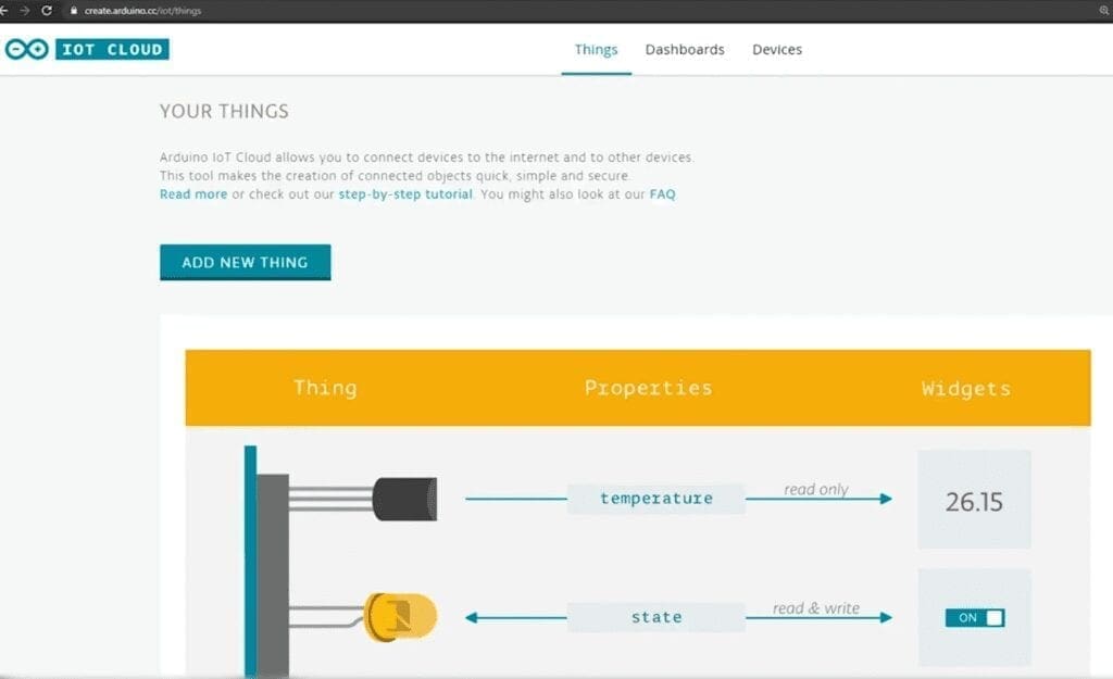
To do that, the first thing we need to do is go to the IoT cloud dashboard and click on add new thing. The thing is like your project and you can configure and associate a device or a board to your thing. Click on the drop-down menu and select configure a new device.

Since we will be using the MKR1010 board, select setup an Arduino device. At this point, they will ask you to download a piece of software that will facilitate the communication between the system and the browser. Simply download and install that. It will automatically detect once the software starts running.
Once it detects the board, you can confirm it and give your device a name. Once you click next, it will upload a sketch and configure the board for you. Once your board is attached to the thing, you can go to the web editor and start coding.

Coding
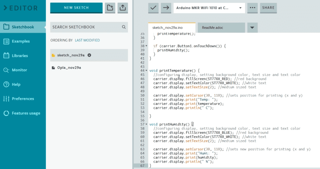
The best thing about Arduino IoT cloud is they provide a skeleton code that contains most of the variables initialized. You just have to add extra variables and the actions. Now let’s take a look at our current project.
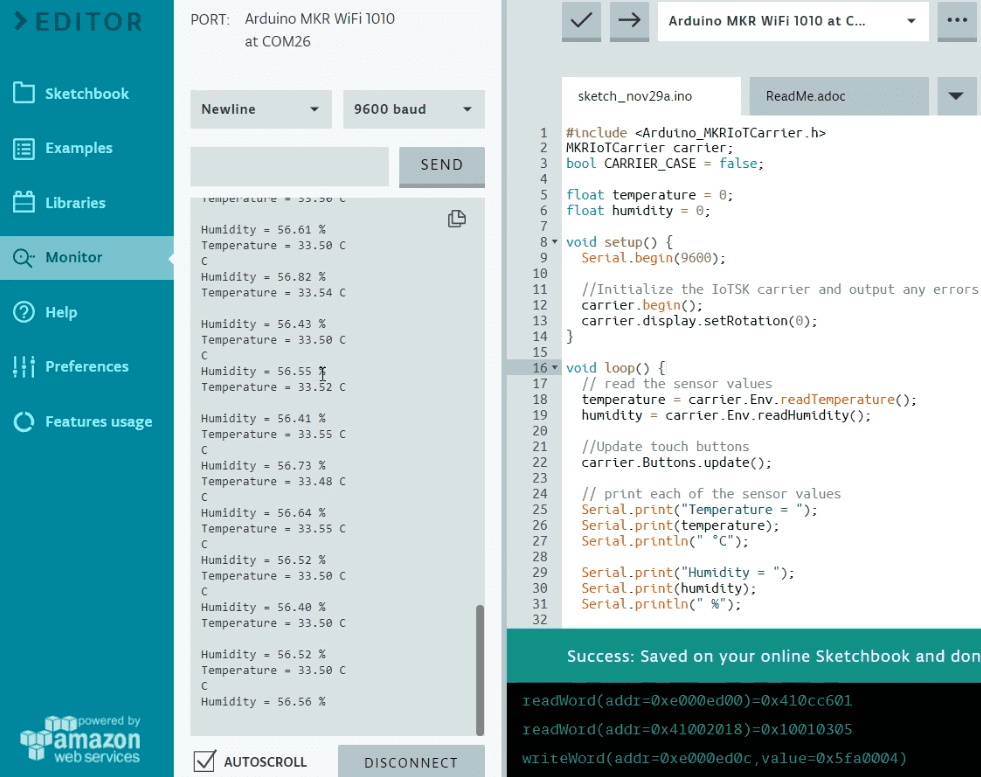
Here, we will be uploading the same code we uploaded earlier. On top, you will see the boards that are connected to your device. You can select Arduino MKR WiFi 1010 and click upload and save.
Once the code is uploaded, you can open the serial monitor by clicking the “monitor” tab. Here you should be able to see humidity and temperature values. You can also tap the button on the carrier board as we did earlier.

Whats Next?
In the next video, we will be showing you how you can create a smart plant watering system using the Arduino IoT cloud! Stay tuned!