Automatic Plant Watering System using Arduino Opla IoT Kit
Hey, guys welcome back to another Tutorial from RootSaid. Last month, I showed you how you can make a Plant Watering System using Arduino nano 33 IoT. In this tutorial, I will be showing you how you can make an advanced version of that project. Here we will make an automatic plant watering system using Arduino Opla IoT Kit.
In the previous post, I showed you everything you need to know about the Arduino Opla IoT Kit. We unbox the kit, showed you different components, how to set it up, and showed you how to upload your first code to your Arduino Opla IoT kit. If you haven’t seen that yet I will leave the link in the description go check it out.
How to Make Automatic Plant Watering System using Arduino?
So what is this Automatic Plant Watering System? This system mainly consists of an Arduino Opla IoT kit, where we connect the moisture sensor and the pump. The moisture sensor will continuously monitor the water content of the soil and the value of the moisture level will be updated to the Arduino IoT cloud.
We can use the Arduino IoT cloud dashboard to check the moisture content and turn on and off a pump that is connected to a water reservoir. We can also set the pump to turn on automatically when the water level goes below a particular threshold.
Automatic Plant Watering System Video Tutorial
If you are a beginner and you are totally interested in building your own robots and electronics projects, then this channel is for you! I am super excited to teach you everything you need to know about what you need to know!

Components Required
For this project, all you need is
- Arduino Opla IoT kit
- A 12-volt pump
- A power source that can provide a 12-volt dc supply
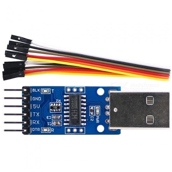
Since Arduino Opla IoT kit is a plug and play kit, you don’t have to solder any components on to it. You can directly connect the moisture sensor using the connector and pump directly to the relay.
I will provide the complete connection details below. Make sure you check that out.
Steps to Make your Arduino Automatic Plant Watering System
Adding Arduino Board to IoT Cloud
Here I’ll be coding the Arduino Opla IoT kit, using the Arduino IoT Cloud. First, we will log in to the console and go to the device tab. From there, you have to add your Arduino Board to the device list.

Here you can see Arduino MKR 1010 board has been already added to the device list. This was shown in the previous video. If you have any doubts regarding this don’t worry guys we have a tutorial specially for that. You can simply click on this link and watch that first.
Creating a ‘Thing’
Now we will create our project for that go to things and create a new thing. Here you will see complete details about your project. First, we will rename our thing. Let’s name it as plant watering system.

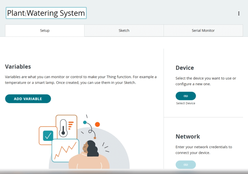
Adding Properties (Variables)
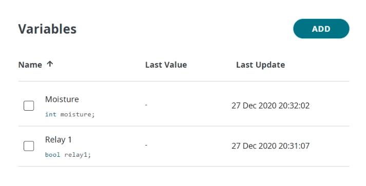
Next, we will add two variables. A boolean variable named relay, to control relay one and an integer variable named moisture to store the value of moisture content.

Creating a Dashboard for Automatic Plant Watering System
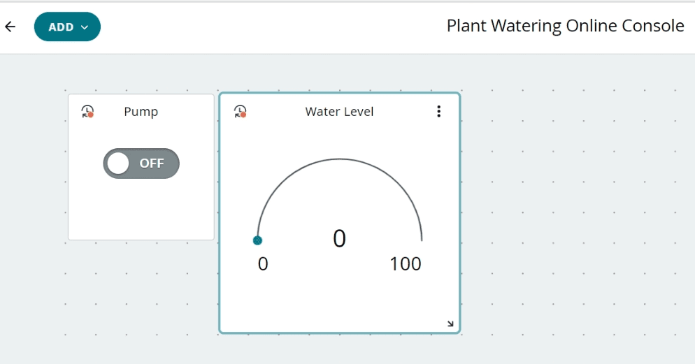
Next, we will create a dashboard and add some widgets and then we will link this widget to our variables. First, we will provide our dashboard with a name. Plant watering online console. To control the relay variable we will create a push-button, and link it to the relay variable. Let’s name it Pump. Then we will add a gauge widget and name it as water level and we will link this widget to the variable moisture.

Linking the ‘Thing’ to the Board
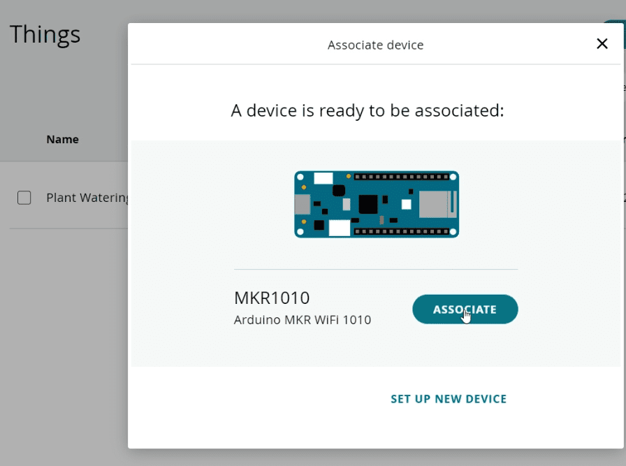
Next, we will attach our MKR 1010 board to this thing named automatic plant watering system. To do that just click on this associate device link and select our board. Now the board has been attached to the thing.
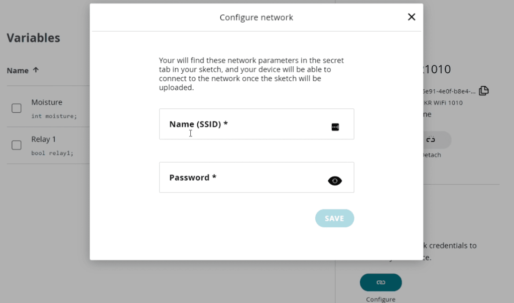
Configuring WiFi
We will have to configure, WiFi network. You can configure the network using the button under the network. There we can provide the name and password of your WiFi network.

Coding your Automatic Plant Watering System
Now simply click on the sketch. This is where will be coding. The advantage of using Arduino IoT cloud is once you have set up your thing and all the variables it will automatically generate a skeleton code which will include all the variables and critical function which is required to run the code. We just have to add extra variables and functions. So guys this is the skeleton code. Now I will be removing all unnecessary comments so that it will look, neet. And here are our final code guys now let’s take a deeper look into it.
#include "thingProperties.h"
#include <Arduino_MKRIoTCarrier.h>
MKRIoTCarrier carrier;

String waterPump1State;

uint32_t lightsOn = carrier.leds.Color(127, 0, 0);
uint32_t lightsOff = carrier.leds.Color(40, 118, 115);

void setup() {
  Serial.begin(9600);
  delay(1500);
  initProperties();
  ArduinoCloud.begin(ArduinoIoTPreferredConnection);
  setDebugMessageLevel(2);
  ArduinoCloud.printDebugInfo();

  CARRIER_CASE = true;
  carrier.begin();
  carrier.display.setRotation(0);
  delay(1500);
}

void loop() {
ArduinoCloud.update();
moisture = map(analogRead(A5), 0, 1023, 100, 0);
delay(500);
}

void onRelay1Change() {

  if (relay1 == true) {
    carrier.Relay1.open();
    waterPump1State = "PUMP 1: ON";
    Serial.println("Pump 1 On");
    carrier.leds.fill(lightsOn, 0, 5);
    carrier.leds.show();
    display_Status();
  } else {
    carrier.Relay1.close();
    Serial.println("Pump OFF");
    waterPump1State = "PUMP: OFF";
    carrier.leds.fill(lightsOff, 0, 5);
    carrier.leds.show();
    display_Status();
  }
}

void display_Status() {
  carrier.display.fillScreen(ST77XX_BLACK);
  carrier.display.setTextColor(ST77XX_WHITE);
  carrier.display.setTextSize(3);
  carrier.display.setCursor(40, 50);
  carrier.display.print("Smart");
  carrier.display.setCursor(40, 90);
  carrier.display.print("Watering");
  carrier.display.setCursor(40, 130);
  carrier.display.print(waterPump1State);
}
Code Explained
First, we are adding the libraries and declaring the variables that we will be using in this project and the LED variables will be used to control the RGB led.
#include "thingProperties.h"
#include <Arduino_MKRIoTCarrier.h>
MKRIoTCarrier carrier;

String waterPump1State;

uint32_t lightsOn = carrier.leds.Color(127, 0, 0);
uint32_t lightsOff = carrier.leds.Color(40, 118, 115);
Then we will initialize the serial communication, communication with Arduino cloud, carrier board, and then prepare the carrier to run the remaining code.
void setup() {
  Serial.begin(9600);
  delay(1500);
  initProperties();
  ArduinoCloud.begin(ArduinoIoTPreferredConnection);
  setDebugMessageLevel(2);
  ArduinoCloud.printDebugInfo();

  CARRIER_CASE = true;
  carrier.begin();
  carrier.display.setRotation(0);
  delay(1500);
}
In the loop function, the value of pin a5 which is connected to the moisture sensor will be read every 500 milliseconds. These values will be mapped to a value between 100 and 0 and will be stored in the variable named moisture. Since this variable is linked to the gauge widget, these values will be reflected on the dashboard.
void loop() {
ArduinoCloud.update();
moisture = map(analogRead(A5), 0, 1023, 100, 0);
delay(500);
}
Onrelay1change function will be executed when there is a change in the relay1 variable which can be controlled using the pump widget on the dashboard. When the pump button is turned on, it will turn on the relay which is connected to the pump and when the pump button is turned off, it will turn off the relay.
void onRelay1Change() {

  if (relay1 == true) {
    carrier.Relay1.open();
    waterPump1State = "PUMP 1: ON";
    Serial.println("Pump 1 On");
    carrier.leds.fill(lightsOn, 0, 5);
    carrier.leds.show();
    display_Status();
  } else {
    carrier.Relay1.close();
    Serial.println("Pump OFF");
    waterPump1State = "PUMP: OFF";
    carrier.leds.fill(lightsOff, 0, 5);
    carrier.leds.show();
    display_Status();
  }
}
That’s it, guys. You can simply upload the code to the MKR1010 of Opla kit.
Connect Everything
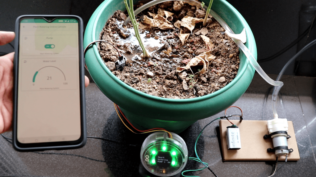
Now, all you have to do is connect everything together. And fix it somewhere it will not be disturbed. Connect the intake valve of the pump to the water reservoir and the outlet valve to the pot containing the plant. Now, insert the moisture sensor into the soil.
Controlling your Plant Watering System from your Mobile Phone(Optional)
Download and install the Arduino IoT cloud application on your mobile phone.
Now open the application and sign with your account. There you should see the dashboard you created earlier. Once we do that, we will be able to control the plant watering system from our mobile. If you look closely, we can see that the moisture content is being updated in realtime as the water content of the soil is gradually increasing.

Now to make it completely automatic, all you have to do is make a little change in the code. Add an if condition to check the value of moisture. If it is below 10, turn on the pump. And if it’s above 10, turn off the pump. The code will be updated here soon.