Making our own Multi-Sensor USB Joystick using Arduino for Gaming and Robotics
Hey guys, in this video, we are going to make an amazing compact joystick using Arduino. We can use this joystick to control our DIY Robots or connect it to your computer and play games with it! Awesome right? So let’s get started!
USB Joystick using Arduino Video Tutorial
Too lazy to read? Here is a complete video tutorial where I explain everything in detail.

Let’s Look at USB Joystick using Arduino and Its Components
First, let me talk a little bit about this USB joystick using Arduino! What it contains and what it can do! The main part of this board is this thumb joystick. This can be used to read horizontal movement, vertical movement, a button press, or a combination of these 3 actions.

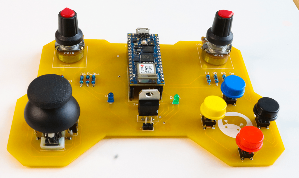
Then we have 4 buttons here which can be used for 4 different custom actions or a combination of 4 buttons. Then we have these pots here. Well, I put it there so that I can use it in future projects like for controlling the position of the camera or something.
Well, that’s not all, do you see this Arduino board over here? It’s not just an ordinary Arduino Nano!
This is an Arduino Nano RP 2040. This tiny little board has an onboard accelerometer, gyroscope, RGB LED, and even a microphone. You can even incorporate machine learning with TinyML, TensorFlow Lite, or Edge Impulse and perform some voice command actions.
This Arduino Board can act as HID (Human Interface Device), as a keyboard or mouse, and send keystrokes through the USB port like a real keyboard. We will be making use of this functionality to make a controller that we can use to control robots and play games on your PC.
USB Joystick Circuit
I’ve always been interested in electronics and technology and making my own PCBs for my projects. I used Altium Designer to draw the circuit and design the PCB. If you are a DIY electronic enthusiast, this is gonna be really useful for you! Altium is an Amazing PCB Designer using which you can design and create your own PCBs for your hobby projects or industrial use. You can download the free trial version from the description down below.
There is something called Altium 365 that comes free with Altium Subscription. With Altium 365, you can design, share, manufacture, and do everything related to your project in the same space without any extra effort. You can also share your designs, and ideas and easily collaborate with your teammates or even clients with Secure Centralized Cloud Storage. So make sure you check it out!
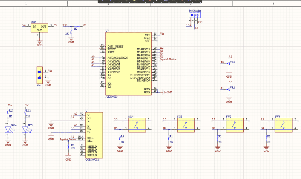
Here we have an Arduino Nano RP 2040 which is the brain of this project.
Here is our joystick, but this might not be familiar to you guys. This is a raw joystick module, it consists of 2 potentiometers and a switch. These are the pins of the first potentiometer, the second potentiometer, and here is the switch! The output of the first pot is connected to analog pin A2 and the second pot is connected to A3 and the switch is connected to D6.
Then we have 4 push buttons connected to 4 digital pins of Arduino – D2, D3, D4, and D5. We will be assigning different key combinations to all these switches while coding. Then we have two potentiometers right here. The output of these pots is connected to two analog pins A0 and A1.
Then we have indicator LEDs at various points. There are two ways to power this board. One is to use an external power source and the other is to use the voltage from the USB port. If you are powering it through Vin, you can provide a DC voltage between 7 to 32 volt, which will be fed to the 7805 voltage regulator. The output of the 7805 is 5V and this 5V is fed to a voltage divider circuit which will convert it to 3.3V.
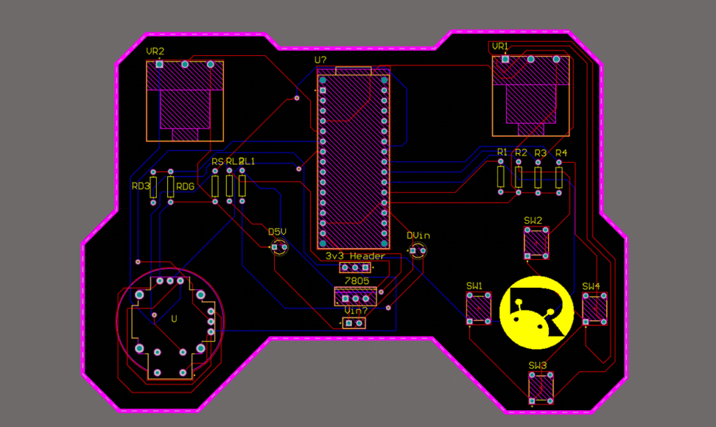
You can easily switch between the two voltage sources using this header right here. The reason why we are converting to 3.3V is, that the operating voltage of Arduino Nano RP 2040 is 3.3V. Providing a voltage greater than 3.3V will fry the chip.
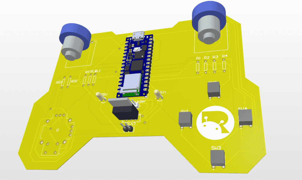
Once the circuit was finished and tested, I designed a compact PCB using Altium, where I can fix all the components neatly. Here you can see routing is on both sides of the board which means it is a dual-layer PCB.
Getting Remote Controller PCB Done
I ordered PCB from PCBWay. PCBWay is a PCB manufacturer specializing in PCB prototyping, low-volume production, and neat and tidy PCB assembly. If you are interested in making your own PCBs for your project, check out the link below. You can get a 5 dollar discount when you sign up using the link below and get an additional 5 dollar discount at the checkout by providing the coupon code PCBWayLab.

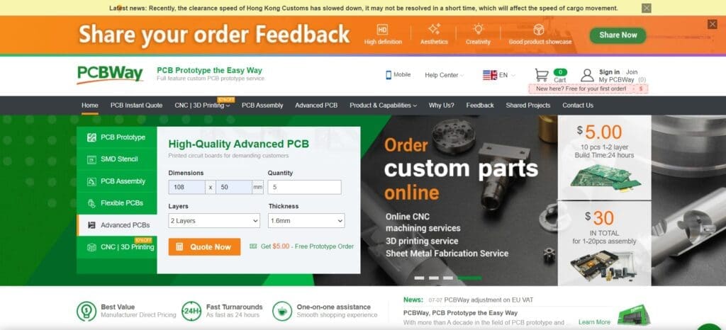
To order your PCB from PCBWay, go to the PCBWay website and fill in the basic board details in the instant order form. From there you will be directed to a form where you can provide more elaborate board details. Update your board information in the PCB specification screen. On the next screen, you should be able to upload your Gerber file and submit it for review. Once the review is completed, all that is left is to add to the cart, make payment, and wait for your PCBs to arrive.
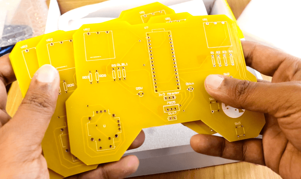
Once you get all the components and the PCB, it’s time for you to solder them together. Solder all the components onto the board and make sure to check the polarity of the components. After soldering the PCB looks like this.
Coding
Now start Arduino IDE and make sure you have installed Arduino Nano RP 2040 board as well as USBHID library. These two libraries are necessary for the Arduino to work as HID.
#include <PluggableUSBHID.h>
#include <USBKeyboard.h>

const int buttonPin1 = 2;
const int buttonPin2 = 3;
const int buttonPin3 = 4;
const int buttonPin4 = 5;
const int ledPin =  13;

USBKeyboard Keyboard;

int button1State = 0;
int button2State = 0;
int button3State = 0;
int button4State = 0;
int pot1 = 0;
int pot2 = 0;
int h_joystick = 0;
int v_joystick =0;

void setup() {

  pinMode(ledPin, OUTPUT);
  pinMode(buttonPin1, INPUT);
  pinMode(buttonPin2, INPUT);
  pinMode(buttonPin3, INPUT);
  pinMode(buttonPin4, INPUT);
  pinMode(A0, INPUT);
  pinMode(A1, INPUT);
  pinMode(A2, INPUT);
  pinMode(A3, INPUT);
  Serial.begin(9600);
}

void loop() {
  button1State = digitalRead(buttonPin1);
  button2State = digitalRead(buttonPin2);
  button3State = digitalRead(buttonPin3);
  button4State = digitalRead(buttonPin4);
  pot1 = analogRead(A0);
  pot2 = analogRead(A1);
  h_joystick = analogRead(A2);
  v_joystick = analogRead(A3);

//*Actions*

if (button1State == HIGH) {
    digitalWrite(ledPin, HIGH);
    Serial.println("Button 1 Pressed");
    Keyboard.key_code('t', KEY_CTRL); //Resize
    delay(500);
  } else {
    digitalWrite(ledPin, LOW);
  }

if (button2State == HIGH) {
    digitalWrite(ledPin, HIGH);
    delay(500);
    Serial.println("Button 2 Pressed");
    Keyboard.key_code('u', KEY_CTRL); //Press CTRL, u
  } else {
    digitalWrite(ledPin, LOW);
  }

if (button3State == HIGH) {
    digitalWrite(ledPin, HIGH);
    delay(500);
    Serial.println("Button 3 Pressed");
    Keyboard.key_code('j', KEY_CTRL); //Press J
  } else {
    digitalWrite(ledPin, LOW);
  }

if (button4State == HIGH) {
    digitalWrite(ledPin, HIGH);
    Keyboard.key_code('v'); //Press V
    delay(500);
    Serial.println("Button 4 Pressed");
  } else {
    digitalWrite(ledPin, LOW);
  }

if ((pot1>=750)&&(pot1<=400))
{
  Serial.println("Pot 1 Min"); // No Change
}
else if (pot1>750)
{
  Keyboard.key_code('-', KEY_CTRL); //Zoom Out
  delay(500);
}
else if (pot1<=400)
{
  Keyboard.key_code('+', KEY_CTRL); //Zoom In
  delay(500);
}


if ((h_joystick>=750)&&(h_joystick<=400))
{
  Serial.println("Horizontal Center"); // No Change
}
else if (h_joystick>750)
{
  Keyboard.key_code(LEFT_ARROW); //Left Arrow Or Go Left
  delay(500);
}
else if (h_joystick<=400)
{
  Keyboard.key_code(RIGHT_ARROW);  //Right Arrow Or Go Right
  delay(500);
}

if ((v_joystick>=750)&&(v_joystick<=400))
{
  Serial.println("Vertical Center");
}
else if (v_joystick>750)
{
  Keyboard.key_code(UP_ARROW);  //Up Arrow Or Go Forward
  delay(500);
}
else if (v_joystick<=400)
{
  Keyboard.key_code(DOWN_ARROW);    //Down Arrow Or Go Back
  delay(500);
}

}
First, we will include the necessary header files. Now we will initialize all the variables, and assign them to pins where the buttons and pots are connected.
In the setup function, we will set the pin mode and initialize serial communication. In the main function, we will fetch the status of each pin using DigitalRead and AnalogRead and store the value in different variables.
The next part is the action, and it’s entirely up to you. You can customize it the way you want. But I will show you how I configured it for playing games on my PC. Here, I have written the condition for each and every button, joystick module as well as two potentiometers – like if the button is pressed, send a particular keystroke.
For example, when you push the joystick forward, send an up-arrow keystroke so that the character moves forwards.
You can also use this joystick to control your DIY Robots as well. Since this board already has an inbuilt Wifi and Bluetooth module, you won’t need to add an additional module for sending or receiving data from the robot.
This is just a glimpse of what you can do with it. There are many useful things you can do, for example, do one thing when you momentarily press the button, another thing when you press and hold a button, and another thing when you release the button, Like I said It’s entirely up to your convenience.
Now simply select the right board and port and upload the code.
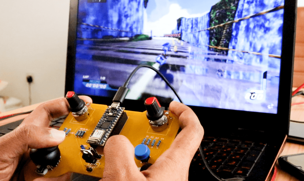
Testing
Now all you have to do is connect the Arduino to your PC using USB Cable, fire up a game and try pressing the button or moving the joystick. Once you get a hang of it, you are never going to let it go.
Ask all your doubts in the comments down below. If you find this video useful, make sure you give this video a thumbs up. Subscribe to this channel for more awesome videos.