This is How I made a Wireless Code Upload Shield for my Arduino Board
In this project, I will be showing you how to make a Wireless Programmer Shield for your Arduino Board and Bluetooth module which can be used to upload codes to your Arduino Board wirelessly without even using a USB data cable for code upload.

As always, I will be giving you complete instructions including the circuit diagram, PCB files if you want to make a PCB, and complete codes so that you can make one yourself.
Why do we need a Wireless Code Uploader for Arduino?
Normally, when we need to change a code running an Arduino that is currently being used in a project, we will have to remove the board from the circuit or PCB, connect it to your computer using a USB cable, upload the code, and put the board back on to the PCB right?
Using this Uploader, you won’t have to take out the board from the circuit or PCB. In fact, you won’t even need a USB cable to upload the code. You can simply upload the code whenever you want using just a laptop or a desktop computer wirelessly. This is called OTA Code upload or Over the Air Code upload.
This is How I made a Wireless Programmer Shield for Arduino – Video Tutorial
![This is How I made a Wireless Programmer for Arduino using HC05 Bluetooth Module [Very Cheap & Easy]](https://i.ytimg.com/vi/6GD3aNFrJ9I/hqdefault.jpg)
Thing You Will Need
- Arduino
- HC05 Bluetooth Module
About HC05 Bluetooth Module
The Bluetooth module used in this project is the HC-05. It is inexpensive and one of the most common modules you’ll see in a lot of other projects. You should easily get one from Amazon or eBay.
How I made a Wireless Code Uploader for Arduino?
We will be dividing this project into two steps.
- The first step is configuring the Bluetooth module.
- The second step is wireless code upload.
There is a tiny difference in the circuit between the first part and the second part. In the PCB, if you are using this PCB I made, you can easily change the connection using jumpers. If you are using breadboards, you can easily use jumper cables to set this up.
Behind the Scene – Making the Wireless Programmer Shield
Designing the Circuit
I have designed a circuit that will allow us to connect the Arduino and the Bluetooth module and do the configuration and wireless code upload without disconnecting the board.

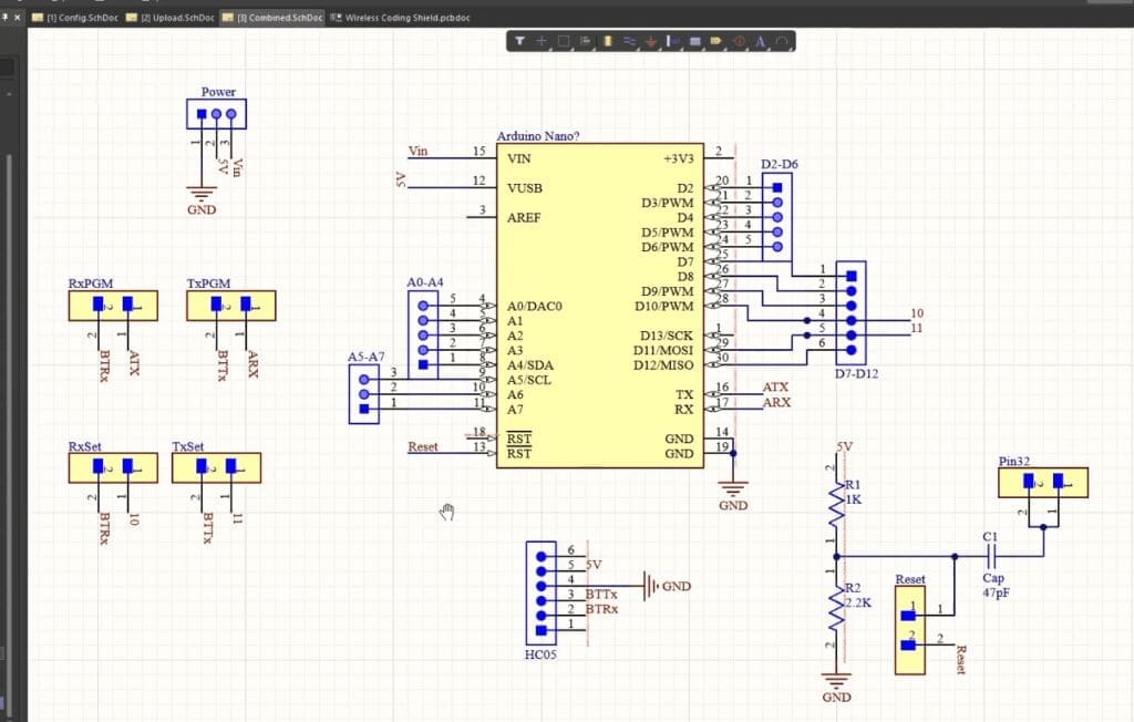
I used Altium designer to draw the circuit and design the PCB. It is a powerful tool that can be used to design and create your own PCBs for your project as well as complex and multi-layer PCBs for industrial use. I will provide the link to the free version in the description. Make sure you check it out!
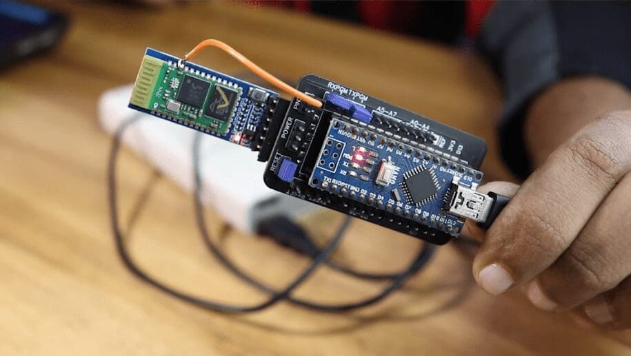
This PCB will actually act as a shield to our Arduino Nano. On top of the shield, we can connect the Bluetooth module. There are headers for almost all the Digital and Analog Pins so that you can use this board as such for your projects.

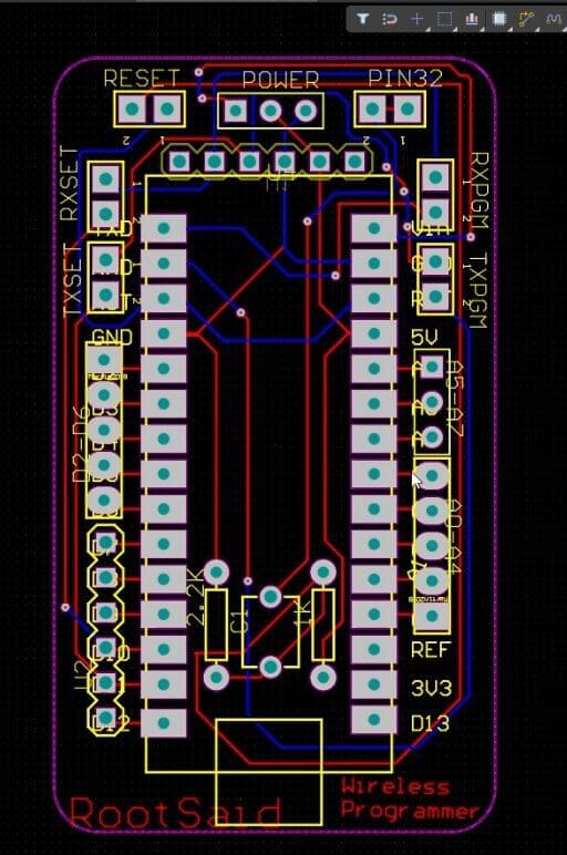
To change it from configuration mode to Wireless programming mode, all you have to do is change the Jumper position. You can power this board using a battery, power adapter, or USB data cable and a power bank which is what I prefer.
Once the circuit was finished, I designed a compact PCB using Altium, where I can fix all the components neatly. Here you can see, routing is on both sides of the board, which means, it is a dual-layer PCB Now all you have to do is export the Gerber.
Getting the PCB Done
I ordered PCB from PCBWay. PCBWay is a PCB manufacturer specializing in PCB prototyping, low-volume production, and neat and tidy PCB assembly.


To order your PCB from PCBWay, go to the PCBWay website and fill in the basic board details in the instant order form. From there you will be directed to a form where you can provide more elaborate board details. Update your board information in the PCB specification screen. On the next screen, you should be able to upload your Gerber file and submit it for review. Once the review is completed, all that is left is to add to the cart, make payment, and wait for your PCBs to arrive.
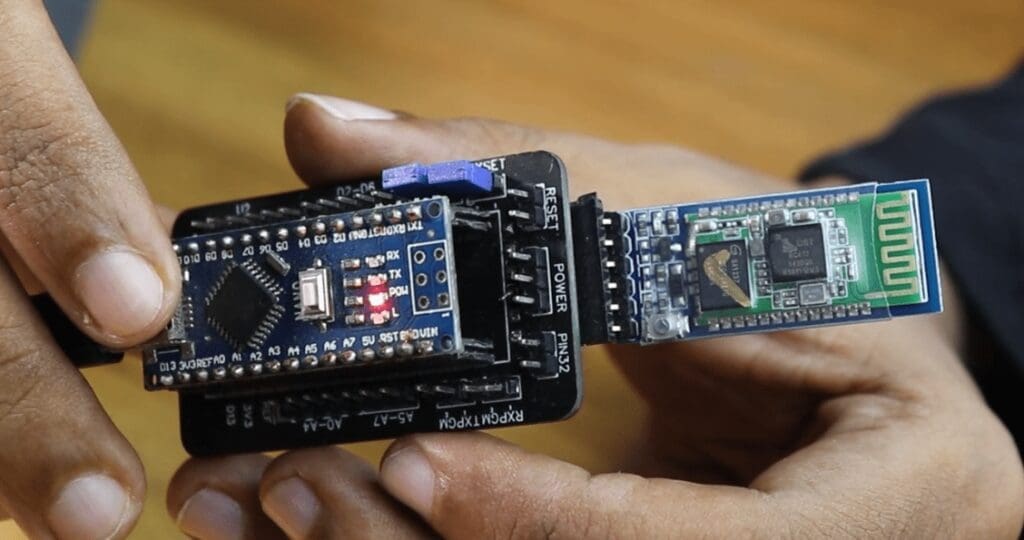
Once you get all the components and the PCB, it’s time for you to solder them together. Solder all the components onto the board and make sure to check the polarity of the components. After soldering the PCB looks like this.
Part 1 – Configuring the Bluetooth Module
Step 1 – The Program Upload Baud Rate
The idea here is to make the HC05 module upload the code to the Arduino when the code is sent to the HC05 module from our laptop. For that, we have to make sure that the baud rate is the same for both the Arduino board and Bluetooth module. The baud rate at which the program is uploaded is different for different boards. For Arduino Nano with Atmega328, the baud rate is 57600 and for the one with Atmega168, it is 19200.
To configure the Bluetooth module, we send AT commands to it. There are multiple ways you can do that.
I decided to use an Arduino to configure the Bluetooth module. To do that, We have to set up a small circuit and program the Arduino to send the commands we provide in the serial monitor to the Bluetooth module.
Step 2 – The Circuit
This is the circuit for configuration.

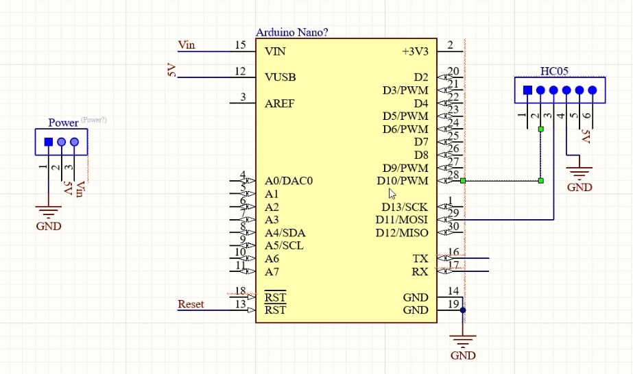
- HC05 GND to Arduino GND Pin
- HC05 5V to Arduino 5V
- HC05 TX to Arduino Digital Pin 10 (soft RX)
- HC05 RX to Arduino Digital Pin11 (soft TX)
If you are using this Shield, Simply connect the headers to RXSet and TXSet and you are good to go.
Step 3 – Setting Bluetooth Module in Command Mode
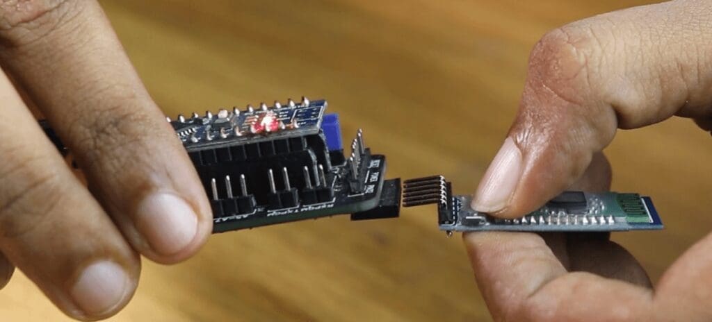
Before connecting the Bluetooth module to the Arduino or the Shield, press this button, and then connect it to the PCB or the breadboard. Hold the key button until the Bluetooth module LED starts blinking at an interval of 2 seconds.
The Bluetooth module LED blinks slower in command mode than the normal mode.
Step 4 – The Code
#include <SoftwareSerial.h>
const byte HC12RxdPin = 10;// Recieve Pin on HC12
const byte HC12TxdPin = 11;// Transmit Pin on HC12

SoftwareSerial RSDBlue(HC12TxdPin, HC12RxdPin); // RX - 11 | TX - 10
void setup()
{

  Serial.begin(9600);
  RSDBlue.begin(38400);//Depends on your HC12 Module, Set Baudrate of Serial Monitor to 9600
  Serial.println("Starting Configuration..");
  Serial.println("Enter AT Commands : ");

}

void loop()
{
  if (RSDBlue.available())
    Serial.write(RSDBlue.read());

  if (Serial.available())
    RSDBlue.write(Serial.read());
}
Now, we can upload this code and once the code is uploaded, we can open the serial monitor and start sending AT commands. These commands will be sent directly to the HC05 Module.
AT
AT+ROLE=0
AT+NAME=RootSaid BT Module
AT+UART=57600,0,0
AT+POLAR=1,0
After successfully issuing the AT commands, you can remove all the connections and that was the end of step 1. Now, our Bluetooth module is ready to upload the code we sent to our Arduino.
Step 2 – Wireless Code Upload to Arduino
Step 1 – The Circuit
In Step 2, connect it as per the schematics shown here. If you are using the Shield, remove the headers from RXSet and TXSet and connect them to RXPGM, TXPGM, and RESET.
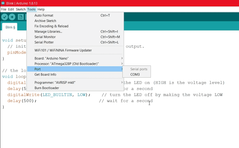
Step 2 – Check the COM Ports in Arduino IDE
Before going further, open up your Arduino IDE and Go to Tools>Ports, and make a note of what is being shown there. We will need that.

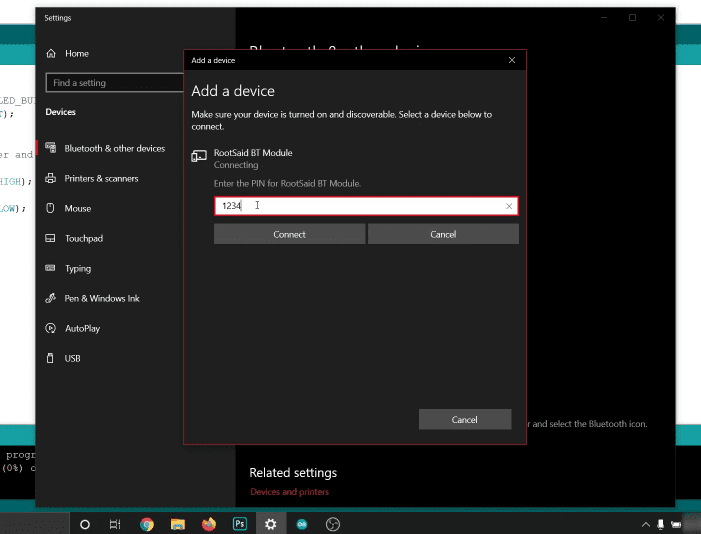
Step 3 – Pairing Bluetooth Module
Now you can open your Laptop’s Bluetooth Settings and scan for nearby devices. It should show you the Bluetooth module. Connect to it, enter the PIN, and pair with it.

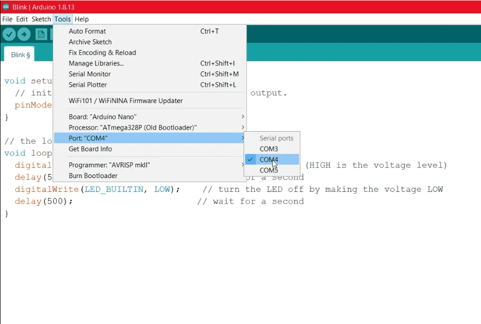
Step 4 – Check the COM Ports in Arduino IDE Again
Once the device has paired successfully, you can open the Arduino IDE again and Go to Tools>Ports. There you should see an extra COM port. That is our Bluetooth module. We will be uploading our code to that port.

Step 5 – No More PC Connections
Now, you can power up the circuit using a battery or a power bank. Now, I will be connecting it to the power bank using this USB cable. Please note that there is absolutely no connection between the board and the computer.
Step 6 – Upload the Code
Now you can open any code, choose the correct board and port and Upload the Code.
That’s it, Guys! From now on you should be able to upload all the codes to the Arduino without connecting it to the computer using data cable.