DIY Long Lasting Voltage Regulator Circuit for Raspberry Pi
Raspberry Pi is simple, handy and cheap yet powerful single board computers of all time. It has USB ports to connect hardware such as pen drive, keyboard, mouse, HDMI port for display out, 3.5 mm port for audio and several GPIO pins to work with embedded projects, all of which can be powered using a mobile charger.
You can even make it portable by simply connecting the mini USB port to a mobile phone power bank so that you can use your pi on the go. But if you connect more USB devices and use the GPIO pins, the power bank will drain off quickly. In this post, I will tell you how i made my own power supply unit using a Lithium Polymer battery and a voltage regulator.
About Our Sponsor – UTSource
To start with, UTSource is a Shenzhen based electronic component distributor and is one of the largest electronic component distributors across the world.

UTSource started as a small business to grow to over 10 million customers with around $150 million in sales. With a huge collection of different products being distributed at UTSource, it can range from semiconductors to transistors to providing design-chain services.

UTSource promises to provide only the best quality products to its customers. All products on the sail are said to be original and certified. Purchased directly from manufacturers and authorized agents.
Things Needed
- Raspberry Pi
- 12 V Lithium Polymer Battery
- LM2596S 20083 Adjustable Voltage Regulator Module
- Multimeter
- A Micro USB Cable
- Some Connecting Wires
- Soldering Iron
Lets Get Started
Step 1 – How to Order Quality Products from UTSource?
Ordering the products from UTSource is easy. First thing to do is head over to the UTSource website and create a free account!

About the product categories, there is a category-based component listed in UTSource with a clear indication of a number of components grouped under each category.

If you wanna see subcategories under each of these categories you can scroll past these main categories and below that you can find the subcategories under each main category.
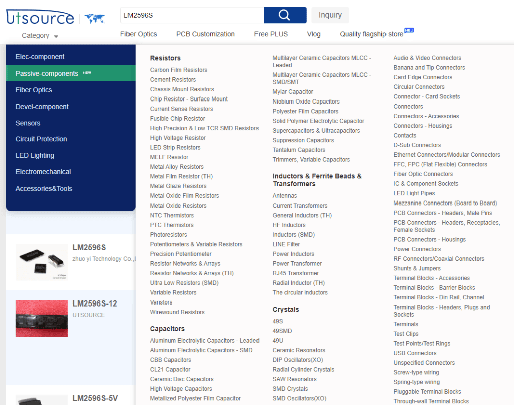
Next thing to do is search for the component you want on the search box.
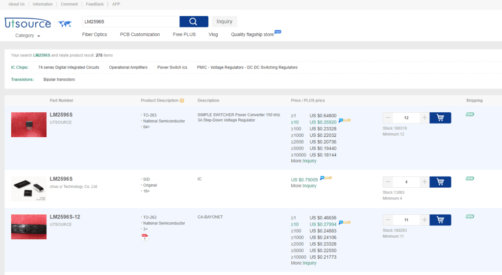
Scroll down the page and find the product you want and add the product to your cart.
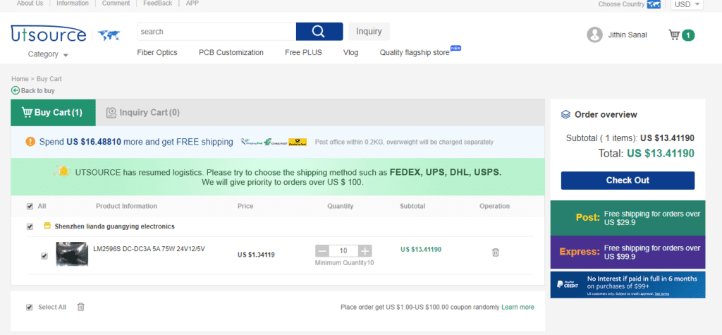
Once you have added all the products to the cart, you can go to the cart to see all the components. In the cart, you can see the estimated charges for different courier services. You can also add or remove more products from the cart.
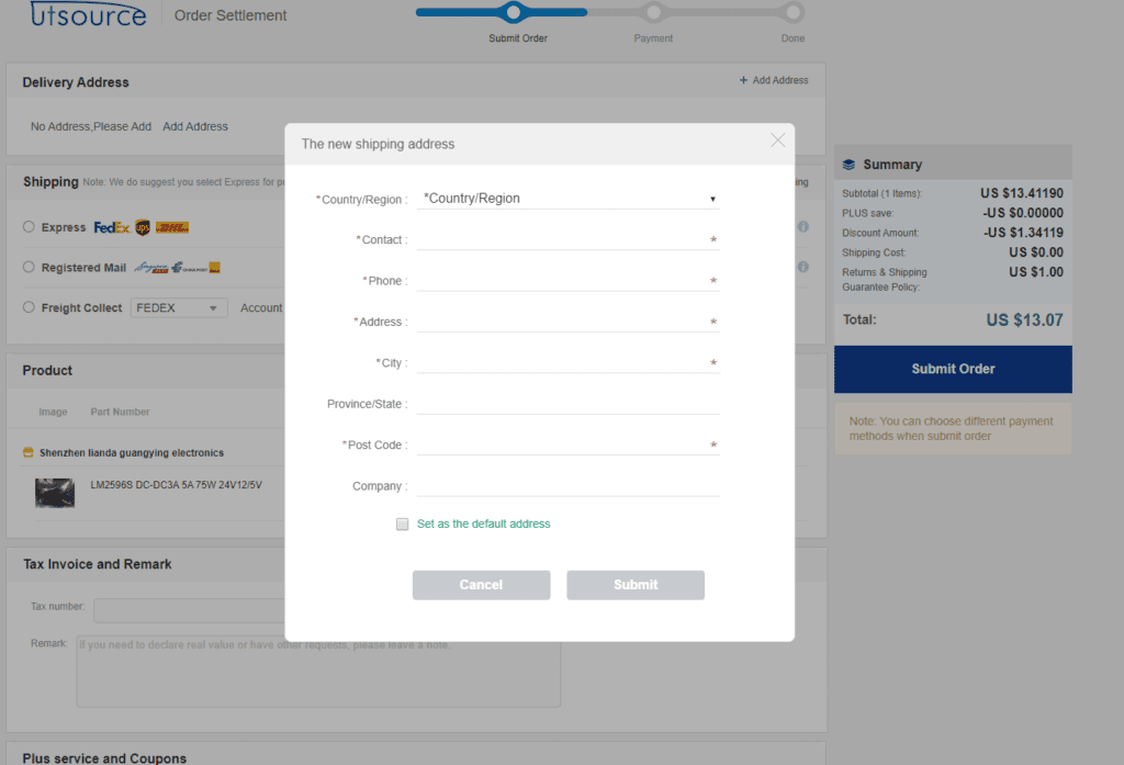
Once you click checkout, you can click on Checkout. Here you should provide the delivery address as well as the Shipping method.
Once it is done, click on Submit order and complete your payment. Thats it! You will get the product within the mentioned time period.
Step 2 – Setting Up Battery
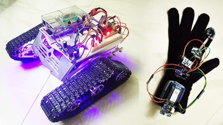
These are high current discharge rechargeable batteries that are used mainly in robotics projects. These motors are mainly used in driving motors such as DC or Servo motors which draws a considerable amount of current, due to its high discharge properties.
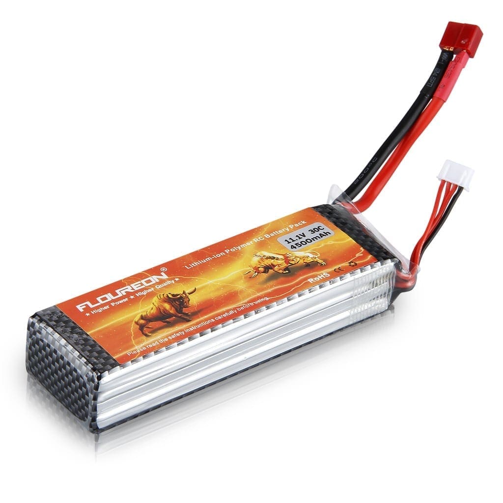
[AdSense-A]However, special care must be taken while using these batteries. special chargers are used to charge these type of batteries. In our project we will be using a 12V LiPo battery to power the Pi
First take the LiPo battery charger and charge the battery. Make sure that it is not kept in direct sunlight. Exposing the battery to direct heat may cause the battery to explode. Once the battery is completely charged, you can connect it to the regulator.
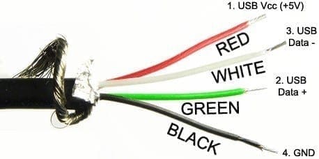
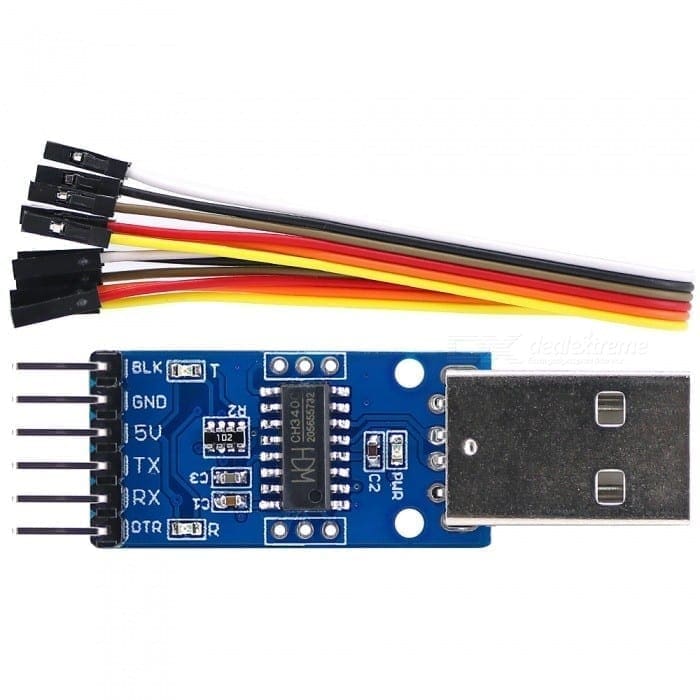
Step 3 – Understanding the USB Pinout
Now connect the pins of the battery to another pair of wire which is to be soldered to the input of the regulator. Connect the +12 V wire to +ve In and the 0 V wire to -ve In. Now connect a multi-meter to the output of the regulator and slowly turn the regulator knob using a screwdriver. You will the voltage reading on the regulator changes.
Adjust the voltage to 5 V +- 1V which is the best voltage level for the working of the Pi. Once the voltage level is checked, battery can be disconnected.
Step 4 – Soldering
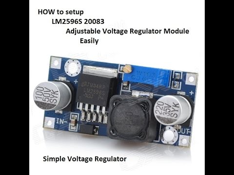
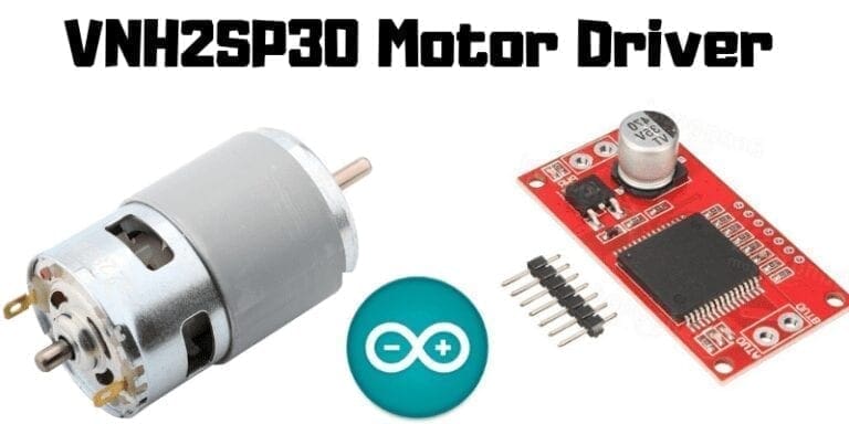
LM2596S 20083 Adjustable Voltage Regulator Module
The lithium polymer battery that we are using can provide a voltage of 12 V where as the pi runs on 5 V. Connecting the board directly to the battery will blow off entire board. So we will need something to convert this 12 V to 5 V and provide a constant 5 V power to this circuit.[AdSense-B]
LM2596S 20083 Adjustable Voltage Regulator is a very handy and easy to use voltage regulators whose output voltage can be easily controlled by turning a screw. Watch the below video to know how.
Now solder two wires on the output of the regulator. We have to supply this 5 V to the micro USB port of the raspberry Pi. Take an old micro USB cable and cut it into half.
[AdSense-B]Now solder the Red (+5V) wire to the +Ve Out of the regulator and Black (GND) wire to the 0V Out of the regulator. Now all you have to do is connect the micro USB cable to the Raspberry Pi and connect the battery.
Ste 5 – Connecting the Display
Depending up on the type of the display, you will have to make some small changes in the circuits. In this post, I will explain the circuits while using the two most common LCD display.
Raspberry Pi 7″ Touchscreen Display
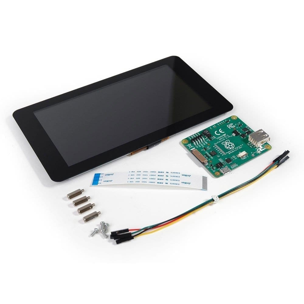
This is the standard easy to use touch screen display from raspberry pi itself. The display is powered using a Micro USB connector in the driver board which inturn powers the Raspberry Pi via GPIO pins. This is a plug and play device if you have the latest version of Raspbian OS.
Raspberry Pi is connected to the display using ribbon cable which is connected to the DSI port. Driver board has two functions – Powering up the screen and converting the parallel display signals to DSI serial signal.
Steps to Connect
- Connect the ribbon cable to the back of the driver board. Also connect the touch screen signal cables to J4.
- Attach the DSI Ribbon Cable to the driver board and connect the other end to the Raspberry Pi.
- Connect some jumper wires from the 5V of the driver board to the Power input pins on the Raspberry Pi.
- Now connect the driver board to the output of the voltage regulator we created earlier. The Driver Board will power up both the display as well as Raspberry Pi.
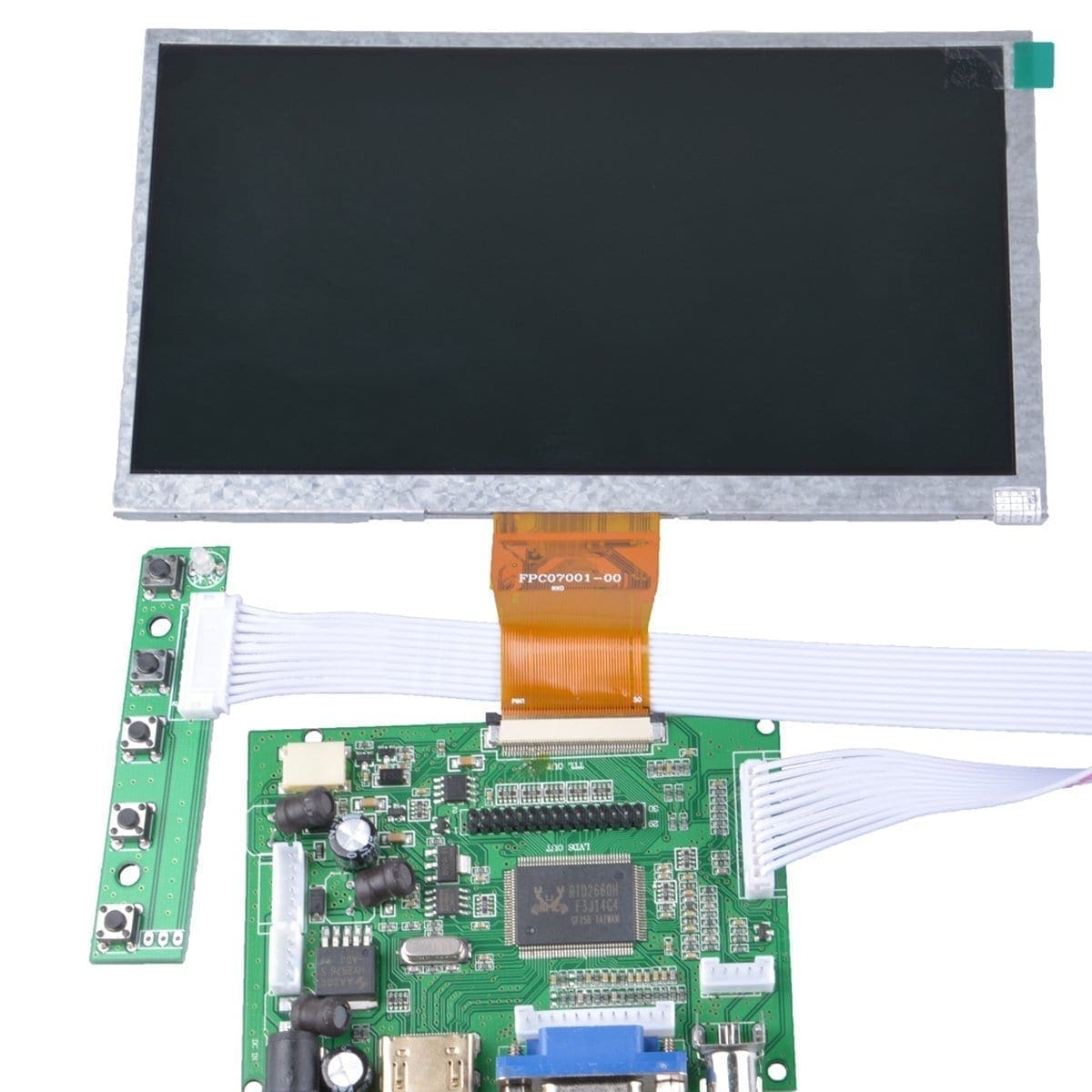
This is most commonly used cheap display board which will work with raspberry pi. This one also comes with a driver board to which we connect the HDMI display port of the Raspberry Pi. If you have HDMI to VGA converter, you can also use that. This board should be connected to a separate 12 V 2 A DC power supply. So we will have to add an extra module.
In our previous circuit, we used only one regulator. But here, we will add one more regulator adjusted to 12 V output in parallel to the previous regulator.
Step 6 – Testing DIY Power Source for Pi
Steps to Connect
- Connect the ribbon cable to the back of the driver board.
- Plugin the HDMI Cable to the driver board and the other end to the Raspberry Pi.
- Connect +5V regulated Voltage to Power input pins on the Raspberry Pi.
- Attach +12 V to the driver board which will power the screen.

This will run the raspberry pi with heavy load for more time than using a power bank. This will be more than enough to power up the Pi and devices connected to the USB port.
Rate the Project
Did you find this page useful? Help us to improve by rating this page.
[RICH_REVIEWS_FORM]
[RICH_REVIEWS_SNIPPET stars_only=”true”]


Why is there no monitoring of the LiPo Battery? These packs have no undervoltage protection so you run these total flat!
You will have some difficulty getting a regulated 12v from a 12v nominal battery. Regulators require their inputs to be above their outputs. This is usually at least 2v. I assume that this is what you are trying to do, it a little difficult to tell. The 5v regulator for pie will dissipate power equal to pi current times 6 volts. Maybe 3 to over 6 watts.