Arduino Voltage Divider 5v to 3.3 V | Level Shifting Explained
Logic levels and Logic level shifting are some of the beginner-level concepts that we all need to master before we take on complex systems. Knowing logic levels will also keep us creative while connecting multiple devices to our systems for multiple inputs and output conditions. Let’s learn in detail what each of them is, with some real-life cases to get you started right away we will also talk about Arduino 5v to 3.3 V Voltage Divider in this tutorial.
Arduino Voltage Divider 5v to 3.3 V
Basically, logic levels indicate the state in which your Arduino pins are in at any given moment. The high and low state that we denote are the voltage level the pins are at, which differs with the type of board as well.
How about a bit more technical knowledge about logic levels then? Let’s see what TTL logic levels, CMOS logic levels, and Arduino logic levels are and their corresponding input/output threshold voltages are in detail. You’ll also learn how each of these logic levels is different from the other and when to use them.
TTL logic levels
As you may already know, there is a great variety of systems that work on 5V TTL (Transistor-Transistor Logic) logic levels. TTL logic primarily works on circuits built out of BJT (bipolar junction transistors) for switching and maintaining logic states. There are preset threshold voltages levels for this logic family as well.
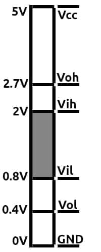
- VOH – The minimum output voltage the TTL device gives for a high signal – 2.7V. It also means that the high output voltage of the device will always be a value equal to or above 2.7V.
- VIH – The minimum input voltage that can be measured as a high signal – 2V. Thus, any voltage that reads 2V or above will be read as 1 or high for a TTL device.
As you can see, there is a voltage gap of 0.7V between the output of first device and the input of the next. This gap is commonly known as noise margin.
- VOL – The maximum output voltage the TTL device could give for a low signal – 0.4V. So for getting a logic 0 or low for the TTL device, the voltage should be less than 0.4V.
- VIL – The maximum input voltage that can be measured as a low signal – 0.8V. It means that every input signal that’s less than this voltage will render a logic 0 while operating the TTL device.
This brings us to an obvious question – what about voltages that are between 0.8V and 2V? For all voltages within this range, the device input is left in a ‘floating’ state wherein the authenticity of the signal cannot be verified.
Signals in this range can also cause the result to be illogical, bouncing from high to low and back indefinitely.
There’s also another way to see the input and output ranges of TTL devices
There’s another voltage standard that’s commonly used in CMOS devices – the 3V CMOS logic level. Let’s check out how it works and the voltages values you need to know.
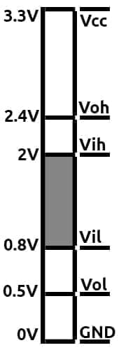
3V CMOS logic levels
A reduced base voltage of 3.3V gives the logic level its name. We now have devices that can run on lower power requirements than the previously standard base voltage of 5V. It’s also made smaller with lesser overall system costs.
While it has a lower base voltage, it is still compatible with 5V devices and can be interfaced without any additional components.
The CMOS device can achieve this because the output high or logic 1 for a 3.3V device is sill be 2.4V or more, more than 2V VIH value that a 5V device needs to register a logic high.
There’s something you need to keep in mind if you are planning to go interface a 5V system to a 3.3V system. Any voltage that’s above 3.6V will damage your 3.3V system’s chip or microcontroller, and thus you should always use a voltage divider circuit to prevent such damages.
Now, we will get back to Level Shifting and Arduino 5v to 3.3 V Voltage Divider.
How much voltage does Arduino need?
Well, this is a question that’s been bugging young enthusiasts and kids who are getting started with Arduino. Well, the answer is not that simple. You have to know the logic levels and input voltage of most of the Arduino boards before answering the question of how much voltage does Arduino need? Check it out!
In the Arduino there are mainly 2 types of voltages. Arduino Voltage Input (Vin) and Operating Voltage
Arduino Voltage Input
In almost all the Arduino boards, there is a pin called Vin pin. That is where we connect the Arduino Voltage Input. The recommended voltage range for that pin is usually 7-12 volt. This voltage is provided to the inbuilt voltage regulator of Arduino! This will convert the Vin to the operating voltage of Arduino, which is usually 5V or 3.3V.
Arduino logic level
Standard Arduino Boards have a 5V logic level while other boards like ESP8266, MKR Family have a 3.3V logic level. This means that when you set the pin high, it will measure either 5V or 3.3V according to their corresponding board.
In the case of older Arduino Boards like UNO and Nano, ATMEGA328 is the microcontroller used in most older Arduino boards which has voltage levels that are a bit different from the ones we discussed above. Of course, 5V is logic 1 and 0 volts is logic 0. The major difference you could spot between the Arduino microcontroller is the shortened invalid region between 1.5V and 3V. Another advantage here is the improved noise margin and a higher threshold for logic low signal, making it easy to interface and work with other hardware.

Most of the latest boards like MKR Family boards as well as Nano 33 IOT boards operate on 3.3V. In those boards, you have to make sure that you provide an input voltage that is less than or equal to 3.3V.
In addition to the boards, sensors also come with such logic levels. For example, an Ultrasonic sensor is a 5V one, but most of the screens available today operate at 3.3V logic levels.
What happens when the voltage is too high?
You can provide a voltage of up to 5V for boards operating under 5V and up to 3.3V for boards that are running on 3.3V. If you provide a voltage greater than the current that Arduino can tolerate, it could damage the board. That is what happens when the voltage is too high.
Level Shifting
You may not always come across this situation, but logic shifting is crucial when your microcontroller uses a different logic level than your sensor. But again, that’s not a necessity in all cases as you’ll see in the coming sections.
Level Shifting – 3.3V devices to a 5V device
This is usually not a problem as the 3.3V device’s HIGH signal (3.3V) will be over the threshold of the 5V device to be considered as it’s HIGH.
While this is mostly the case, there are exceptions to this rule. Some Neopixels require logic level shifting because, in them, 3.3V signals don’t work well running at 5V. In these cases, we have to perform a level shifting to up the voltage.
Level Shifting – Arduino Voltage Divider 5v to 3.3 V
You should be really careful while doing experiments that involve sending high voltages to systems that have a lesser maximum voltage.
For 3.3V devices, the maximum voltage they can accept at their pins is around 3.6V. Anything above and you run the risk of damaging your device. This is the time, we must perform level shifting to down the voltage from 5V to 3.3V so that the 3.3V device will not get damaged.
Here’s one real-life example: connect an Ultrasonic sensor (5V) to an ESP8266. The HIGH signal on the trigger pin will emit an ultrasonic signal and after getting a bounced back signal, it will register a HIGH at the echo pin which lets the microcontroller measure the distance from the object based on the time between the trigger and echo.
The trigger will work fine, as 3.3V is well above the threshold voltage for the 5V ultrasonic sensor to register a HIGH, but the Echo signal when registered HIGH will need logic shifting as the voltage then will be 5V which is much greater than what the microcontroller can accept.
Arduino Voltage Divider 5v to 3.3 V – 2 Methods
Voltage divider
This is the easiest of ways to ensure your 3.3V devices works well connected with 5V devices. What we essentially do here is add suitable resistors to drop the voltage to make it safe for all your devices to function properly.
As you can see from the image, the output that comes from the divider is the one that comes out in the middle. We can now calculate how much the voltage drop is across each resistor. In each situation, the output voltage we get will be well within 3.3V.
Here’s how you calculate the new Voltage = (R2/(R1+R2))*V.
Using a Bi-directional logic level shifter
If you wish to do away with resistors, here’s another option you might consider to sort the issue quickly. The resistor model is suitable when you have a simpler system and you are comfortable doing all the voltage calculations to get your system to work within safe limits.
A device for bi-directional logic level shifting is inexpensive and basically turns a 5V supply into a corresponding 3.3V signal. So when you connect a higher voltage (anything above 3.3V) to the HV pin of the shifter and the low voltage device to the LV pin of the shifter, any signal received by the pins will be safely output at the other pin within safe working voltage.
Summing up
Logic levels and logic level shifting are really simple and effective concepts when it comes to designing projects that are robust, concise systems that are easy to understand and simpler to operate.