
Spinel Crux – Gesture Controlled Robot for Wireless Surveillance – Tutorial Part 1
In this series, we will build Spinel Crux, a Gesture Controlled Robot which can travel through rough terrain and can be controlled using hand gestures. To control the robot, we will be using control glove, which will have an accelerometer and a flex sensor to control the status and the direction it should move. The flex sensor activates the Gesture Controlled Robot robot and the tilt of the accelerator determines the direction it should move.
Gesture Controlled Robot Tutorial
For your convenience, I will be dividing this post into two parts. In the first part, I will show you how to make the control glove using Arduino, flex sensor and accelerometer.
In the second part, I will show you how to build the Gesture Controlled Robot – Set up the chassis, installing Raspberry Pi, coding, connecting Raspberry Pi with motor Driver IC and driving it using hand gestures.
We can build a robot using Raspberry Pi as well as Arduino. In this tutorial, we will be using Raspberry Pi. In the future, I will show you how to build one using Arduino.By the end of this tutorial, you will be ready to make this on your own.
Video Demo

Click the Subscribe YouTube button below for Demo and Complete Tutorial
Components Used
First, you will take a look at the components.
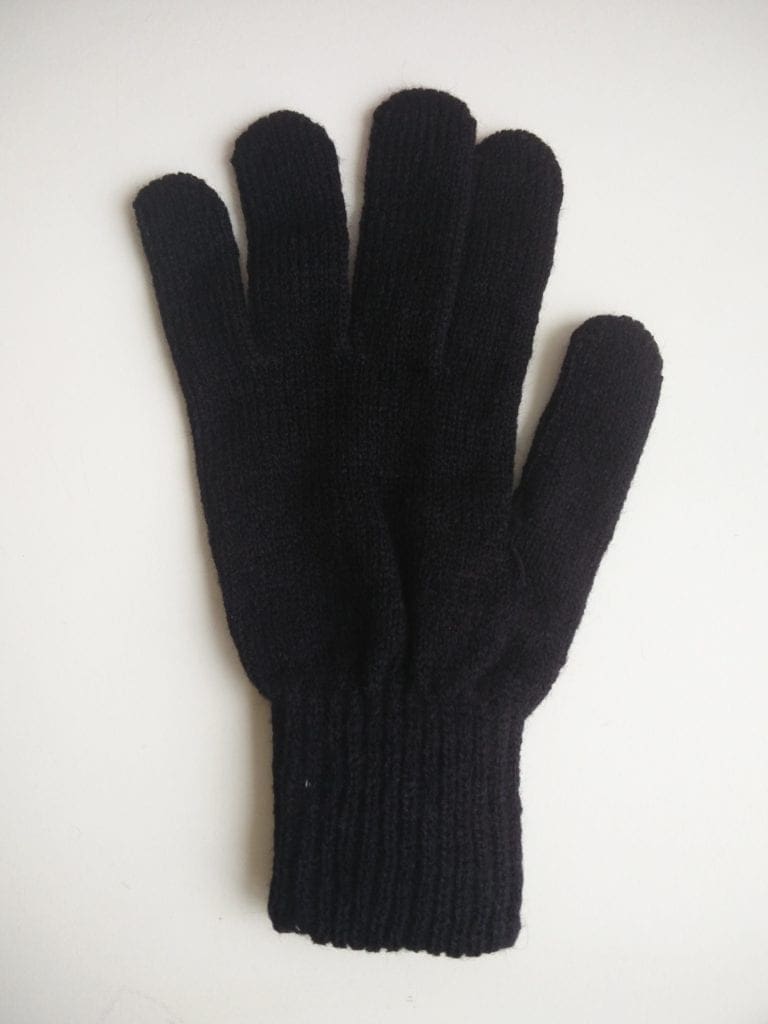
- Gloves
- Accelerometer
- Flex sensor
- Any Arduino Board with Wi-Fi connectivity
- Robot chassis
- L293D motor driver
- Raspberry Pi or another Arduino ( for controlling the robot)
- Breadboard
- Resistor
Before going through the tutorial, let us take a closer look at the components we are using in this project.
Video Tutorial Released

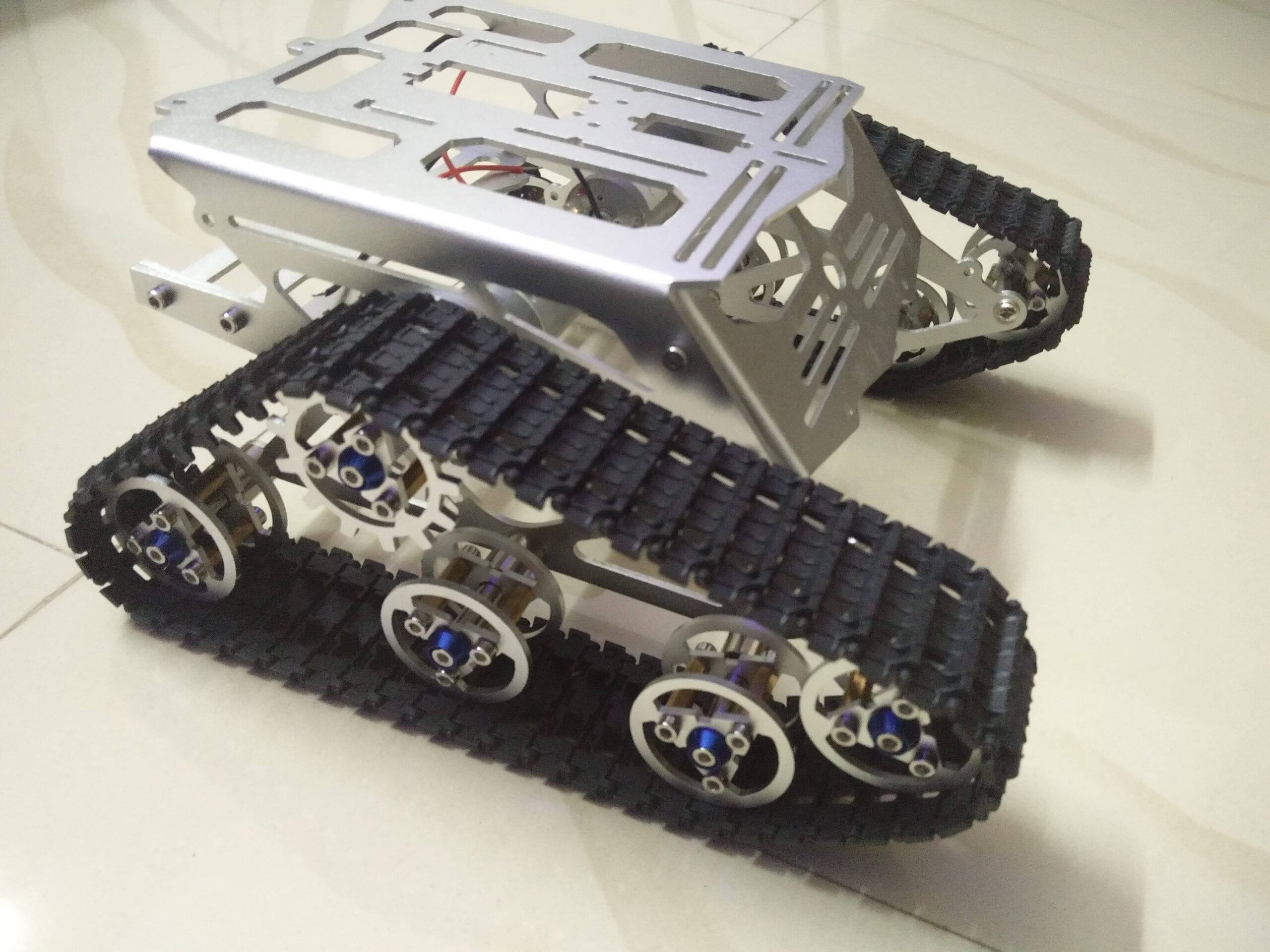
Robot Chassi – DIY Smart Robot Tank Chassis Kit

The chassis I used for making this Gesture Controlled Robot is an awesome cool looking kit. I got this kit banggood.com. Not only this one, they have so many types of robot frames, motors and almost all the sensors for doing arduino, raspberry pi and other electronics and hobby projects. You will get all these things for a cheap price with really fast and quality shipping.
And the great thing about this kit is they provide all the tools you need to assemble the frame together.
Get your DIY Tank Kit From BangGood

These are some of the best robot chassis available for you to build this project. Check out the link below.
http://bestonlinedeals.today/best-robot-chassis/
Accelerometer
An accelerometer is a sensor which can be used to sense the acceleration due to gravity on various axis acting on an object. Using this we can easily calculate the tilt of an object with respect to the Ground. We will driving our Spinel Crux using the X and Y tilt analog values.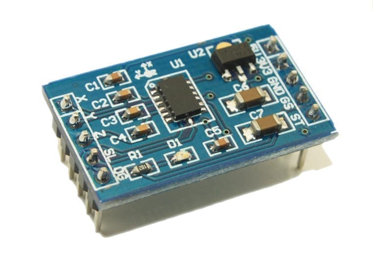

Here I am using MMA7361 accelerometer to control the direction of our Gesture Controlled Robot; you can use any accelerometer which will give analog values in X and Y direction. The reason why I am using this accelerometer is, we can provide 5 volts as well as 3.3 volts as Vcc to this accelerometer. since I am using Arduino MKR1000, I can connect 3.3 Volt directly from the Arduino. It is also small very lightweight and can easily be connected to Arduino and Raspberry Pi without much complication. if you want you can buy this accelerometer for a cheap price from banggood.com.
Flex Sensor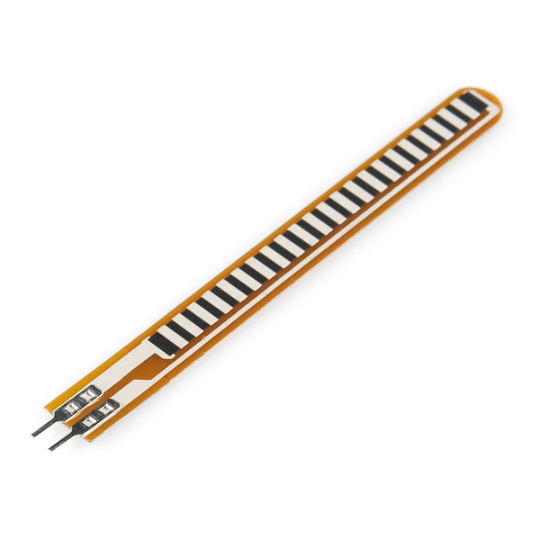

You might know what a flex sensor is. It is a long sensor which changes its electrical properties when it is bent. The length of the flex sensor that I am using for our project is 2.2 inches.
There are two output pins – one is for ground and the other is for the analog output. As the sensor is flex the resistance varies across the terminals. That is it increases and decreases. When the sensor is flat, it gives the normal resistance and when it bends towards level to 45 degree resistance increases and when it brand towards 90°, resistance increases. When it bends towards the membrane, resistance decreases. Coming to the output of the flex sensor it gives the analog value in a wide range, which can be converted to the digital value of zero and one with ADC converter.
Application of the flex sensor is spread across various fields like Robotics, gaming, medical devices, physical therapy and much more applications. In this project, we will be using this flex sensor to turn on and off our Spinel Crux.
Arduino
Next, you will need an Arduino Board, which will receive the output of the flex sensor and accelerometer, process it and send it to our Gesture Controlled Robot as udp packets. You can use any Arduino board with Wi-Fi connectivity or you can use a board without WiFi, like Arduino Uno and connect a Wi-Fi Shield to it and connect it to WiFi.


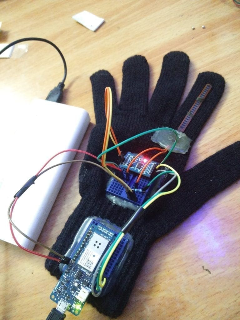
Here I will be using Arduino MKR1000 to make our controlling gloves.
Spinel Crux – Gesture Controlled Robot for Wireless Surveillance – Tutorial
Step 1 – Testing the Components[AdSense-C]
This step is simply for testing the components. If you are sure you are using good components and they are working properly you can simply skip this step and go to Step 2.
Before connecting everything together, it is a good thing to test the components separately. so let us start testing the flex sensor and the accelerometer.
Flex Sensor
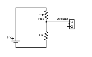
As mentioned earlier flex sensor is a long strip which will change its resistance when it is bent. It will give out an analogue value which can be fed to the Arduino. This can be done using a simple voltage divider circuit.
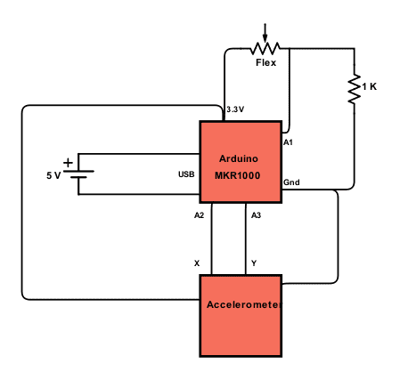
Set up a circuit as shown below and connect output to an analogue pin of your Arduino.

Now let us see how to analog values look like.
Now copy the below code to your Arduino IDE, select the correct port and board and click upload.
int x;
void setup()
{
Serial.begin(9600);
}
void loop()
{
x = analogRead(A0);
Serial.print("X = ");
Serial.println(x);
Serial.println("");
delay(250);
}
Once the upload is complete fire up the serial monitor.
If everything is done correctly it will show you some analogue values and the screen. Now try bending the flex sensor. The values on the screen should change.
Accelerometer
Now it’s time to test the accelerometer. I have already made a post which explains everything you need to know about accelerometer MMA7361. In this post I have mentioned the steps to test the answer draw metre by reading analogue values out of it. Click on the below link to test your accelerometer.
Step 2 – Making the Gloves
Now it’s time to make our controlling Gloves. For that, you will need a gloves, accelerometer and the flex sensor.

All you have to do is attach the flex sensor to your pointing finger and accelerometer on top of your hand (gloves). You can fix everything the way you want it everything is up to you. Anyway I will tell you how I made my controlling Gloves.
Connections

I had some spare breadboard lying around here, so I thought of using it than making a PCB to connect all these things together. These breadboards were small and they fit neatly on top of the glove.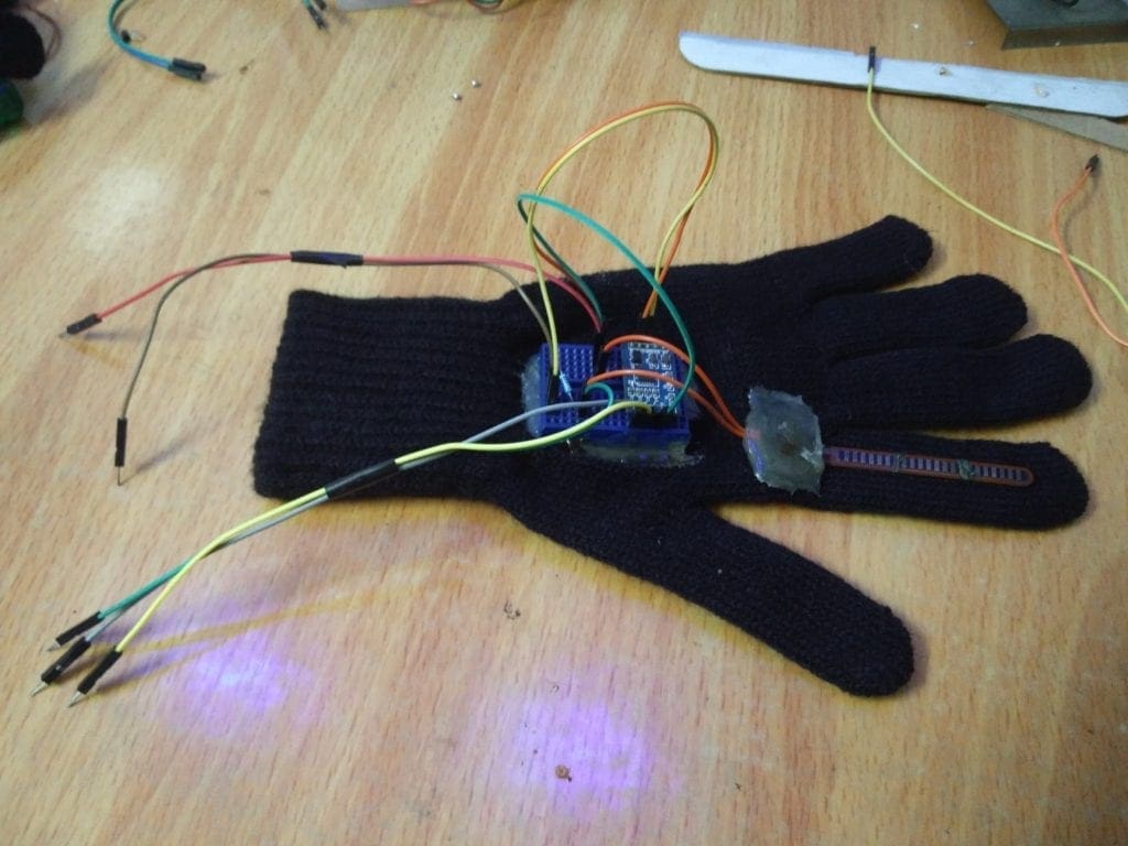

Then I used some black insulation tape to fix the flex sensor on top and bottom and used glue gun to fix it permanently. Then I used a needle and string to stitch some slots to hold the flex sensor in place along the finger.

Step 3 – Power
This is very important and you should be very careful while providing a voltage to the whole thing. The step varies from board to board and sensor to sensor.


As mentioned earlier I am using Arduino MKR1000 and MMA7361 accelerometer. We can provide a 5 volt power supply to arduino via its USB port and use its 3.3 volt output the power the accelerometer and the flex sensor. So I will be using a power bank, to power up the whole circuit of the control glove of the Spinel Crux.
Unlike some arduino boards like arduino UNO that can tolerate a voltage input of 9 volt and can withstand voltage of 5 volt in and out of the GPIO pins, boards like arduino MKR1000 and node MCU, can tolerate only upto 3.3 volt in it’s GPIO pins.
Providing a voltage more than that could burn of your board.
Step 4 – The Code
Now it’s time to upload the code to the Control Glove of the Spinel Crux Gesture Controlled Robot. The code I made is available on GitHub and you can download it by following the below link.
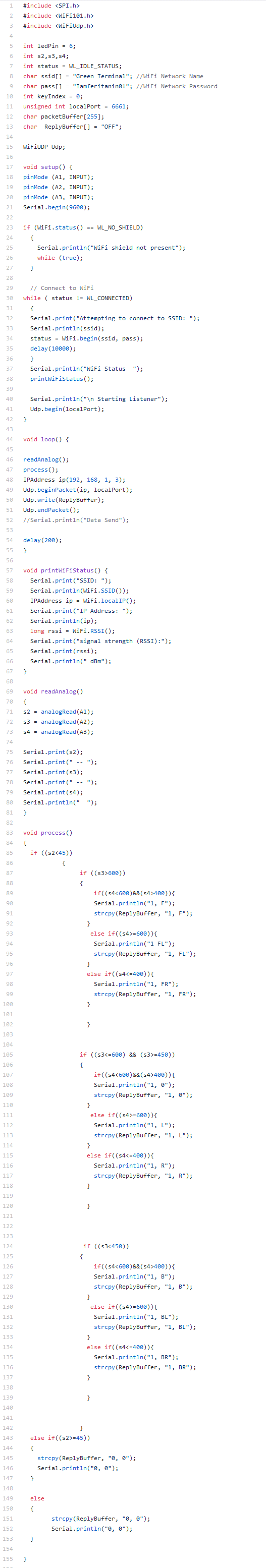

[AdSense-A][Download]
The parts of the code you should change
You should change some part of the code for the code to work properly with your WiFi Network.
char ssid[] = "RootSaid"; //WiFi Network Name
char pass[] = "www.rootsaid.com"; //WiFi Network Password
Here you should provide your WiFi name and password.
IPAddress ip(192, 168, 1, 3);
And this should be the IP address of the listener (Spinel Crux Robot which we will cover in the next part)
Another thing you may want to change is the threshold values to which it should respond.
Step 5 – Testing
Now let us test everything. Start your PC and download the below software (For Windows). This software will help you to capture and display the UDP packets which is sent to that IP Address to a particular port. [AdSense-A]
First of all edit the code of our control glove
Edits
- WiFi SSID
- WiFi PAssword
- and IPAddress ip(192, 168, 1, 3); —-> Enter the IP Address of the PC
Then upload the code to your Arduino.
Click Here to Download the software for windows.
Now start the software, enter the port number (6661) and click on start server.
Put on your glove and start testing. You will see the UDP packets that is sent from the Arduino.
In the next Part, I will explain how to build the Robot.[AdSense-B]
Rate the Project
Did you find this useful? Help us to improve by rating this page.

Hi i need a help i am doing this project as my final project i need the circuit connection, schematic diagram for it and also need a little help in code. Please reply as soon as possible.