How to make a Burglar Alarm | DIY Burglar Alarm Tutorial
Hey guys, welcome back, In the previous post, I told you how an IR sensor works and how to make a line follower using an IR sensor. In this post, i will show you how you can make a Simple DIY Burglar Alarm using an IR sensor and a Buzzer without using any micro controller or complicated coding.
DIY Burglar Alarm Components Needed
To set this up, All you need is
- IR sensor
- Breadboard
- Buzzer
- Some connecting Wires
- 5 Volt Power Adapter
IR Sensor Burglar Alarm Video Tutorial
DIY Burglar Alarm Tutorial


Sponsor Link
This Project is Sponsored by UTSource. UTSource is a professional electronic components supplier.
About IR Sensor
If you are a beginner and new to Electronics and Robotics, you might have heard the name of this sensor multiple times – The IR Sensor.
IR sensor mainly consists of an IR transmitter (IR LED) and an IR receiver (Usually a photodiode).

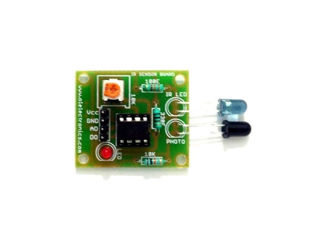
Most IR Sensor will be having 3 pins. The VCC (5V), GND (0V) and Vout (Output Voltage).
VCC will power up the sensor circuit. The Vout pin will give us an output voltage when the IR light is reflected back to the photodiode.
IR LED always emits IR rays to the direction it is pointing to. Now let us bring it closer to a surface. When the IR rays hit a surface, some rays will be reflected back depending upon the color of the surface.
Means, the brighter the color is, the more IR will be reflected back. Darker the color, more IR will be absorbed by the surface and lesser IR rays will be reflected back.


These reflected rays are received by the Photodiode and depending upon the intensity of the received IR rays, the resistance of the photodiode varies which will, in turn, varies the output voltage.
Thus it is possible to sense the brightness of the surface by looking into the reflected IR rays.
DIY Burglar Alarm
So Now you know how an IR sensor works. We will start building our Burglar alarm.
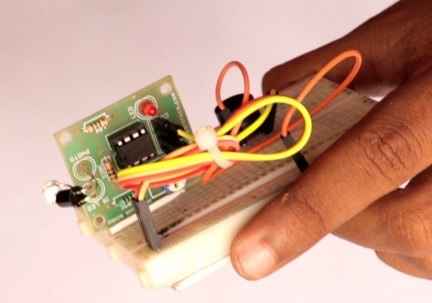
This project is very simple. You wont need more than 1 minute to set this up. This is how we set up the entire circuit.
Here I will be bending the legs of the LED and photodiode so that they are facing each other. I will show you why I am doing this in a minute.
Connections – Burglar Alarm Circuit
The 5 V supply is connected to the IR sensor and the IR sensor Output is connected to the Buzzer.
IR Sensor
Vcc – 5V
Gnd – Gnd
Vout – +ve of Buzzer
Buzzer
+ve – Vout of IR Sensor
-ve – Gnd
You can use a breadboard to connect all of them together.
Fixing it on the Door
I have cleaned all the connection using a zip tie and this is what it looks like.

Now we can fix this on the door frame and power it up.
Now we need something to block the IR rays from LED from reaching the photodiode. For that you can use a black cardboard or a tape.

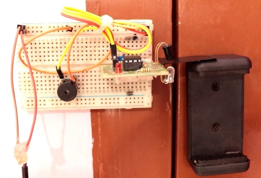
We can fix this on the door in such a way that when the door is closed, it will be placed in between the photodiode and the IR LED.
Burglar Alarm Working Explained
When the door is closed, the photiode will be facing the black surface and no IR rays will be reaching the photodiode and hence the output of the ir sensor will be Zero.
When the door is opened, the photodiode will be facing the IR LED and the IR rays will be directly hitting the photodiode. This will cause the output voltage to go high and the buzzer connected to the output of IR sensor will start to beep.
New to Robotics?
We have a beginners guide on “Getting Started with Robotics” which will give you a kick start in this field. Check out our free video tutorial below for a brief introduction.

Top Arduino Projects You can Try this Summer Vacation

Top Robotics Projects You can Try this Summer Vacation

Did you find this page useful? Help us to improve by rating this page.
[RICH_REVIEWS_FORM]
[RICH_REVIEWS_SNIPPET stars_only=”true”]