
Line Follower Without MicroController for Beginners
Line Follower… Well.. What else is new?? IR Sensors, motors, chassis, arduino/pic or any other microcontroller, simple pieces of codes.. They are all common right?
How about building a cheap, basic and simple line follower without using arduino or pic? A line follower without microcontroller at all. No Coding ;).

Here, we will build a simple line following robot using just an L293D motor driver and two DC motors. Without wasting time. Let get down to it.


Sponsor Link
This Project is Sponsored by UTSource. UTSource is a professional electronic components supplier.
Getting Started with Robotics?
Want to learn Robotics from Scratch? Here is an awesome guide for you to get started with robotics (Free Video Tutorials Included).
Building a Line Following Robot without Microcontroller
Components needed
- Robot Chassis
- L293D/L298N Motor Driver – Get it Now
- IR Sensor – Get it Now
- 2 DC Motors – Get it Now
- 9 V Battery – Get it Now
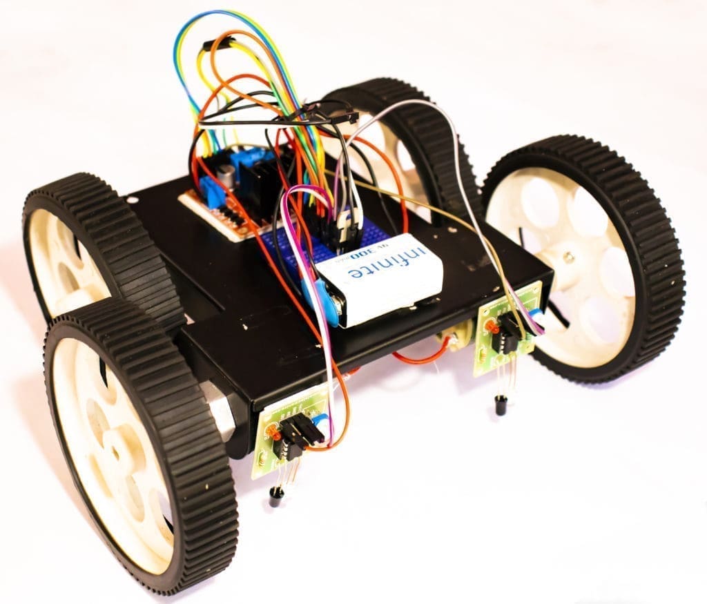
The Chasis
The first thing to do is build a chassis for WiFi Robot using Arduino. You can build it the way you like. The only thing you should keep in mind is, it should have enough space for L293D Motor Driver, and a battery. For our project, I will be using a 12V LiPo Battery. You can use foam board or aluminum sheet or wood piece for building the base.

Or if you have raw materials, you can build one on your own using Cardboard, acrylic sheet or wood.
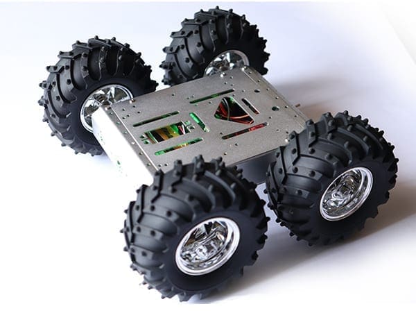
These are some of the best robot chassis available for you to build this project. Check out the link below.
Get the Best Robot Chassis Online
IR Sensor
As mentioned earlier, our line following robot will be following a black line in a white background. So we need something that will ‘see’ the line and tell the line follower to follow the line or to turn around if it is going away from the line. For this purpose, we will be using an IR (Infra Red) Sensor.
This IR sensor mainly consists of an IR transmitter (IR LED) and an IR receiver. IR LED always emits IR rays to the direction it is pointing to. When the IR rays hit a surface, some rays will be reflected back depending upon the color of the surface. Means, the brighter the color is, the more IR will be reflected back. Darker the color is, more IR will be absorbed by the surface and lesser IR rays will be reflected back.
These reflected rays are sensed by the IR receiver and depending upon the received IR rays, the resistance of the receiver varies which will, in turn, varies the output voltage.
Thus it is possible to sense the color of the surface where the robot is running by looking into the reflected IR rays. So it is very easy to measure how bright the surface is which will make it easy for us to track the line.


There are so many cheap IR sensors available online; you can purchase any of them. You will need at least two of them for making the line follower robot.
Setting up the IR Sensors
Most of the individual sensors will be somewhat like this.


It will be having 3 pins. One for VCC (5V), GND (0V) and Vout (Output Voltage). VCC will power up the sensor circuit. The Vout pin will give us an output of 5V when the IR light is reflected back to the IR detector.
H Bridge and L293D Motor Driver
An H-bridge can be any switching circuit using Bipolar Junction Transistors (BJT) or Field Effect Transistors ( MOSFET or MESFET) which allows a voltage to be applied across a DC motor without making physical or hardware changes in the circuit. H Bridge circuits are widely used in the field of robotics to switch the direction of DC motor rotation as well as for creating square waves for so many purposes.

Click Here to Learn the working of an H Bridge Motor Driver
L293D is a 16 pin compact H Bridge circuit available in the form of an IC. The advantage of using L293D is, since there are two H Bridge circuits in one IC, you can control two DC motors simultaneously using a single chip. In this project, we will be using this IC to drive the motors in our line following robot.
Connections
Connect all the components as shown below.
- Vin of IR Sensor —–> 5 V
- GND of IR Sensor —–> GND
- Vout of IR Sensor 1 —–> Enable Pin of Motor 1
- Vout of IR Sensor 2 —–> Enable Pin of Motor 2
- Vcc1 of L293D —–> 5V
- Vcc2 of L293D —–> 12V
- GND of L293D —–> 5V
- S1 of Motor 1 ——> 5V
- S1 of Motor 2 ——> 5V
- S2 of Motor 1 ——> GND
- S2 of Motor 2 ——> GND
The Connections of Line Follower Without Microcontroller are pretty simple and you can do it in 10 minutes.
Power Up
Once it is done, you can now power up your bot and put it on a white surface with a black line. Adjust the sensitivity of the IR sensor and Your Line Follower Without Microcontroller will start to follow the line.


The article seem to have some mistakes:
The text under “chassis” mentions an Arduino, which clearly should not be in this project.
The parts list does not contain any kind of battery.
Under teh heading Connections, “Vcc1 of L293D” is mentioned twice, and the L293D is only connected to Voltage and no input?
The project seems really nice, could you please update this?