Let us do something fun during this weekend shall we? Something less costly and easy for everyone to do. This time, why don’t we play with lights? Let us build a cool blue Automatic Lights just like neon, that will turn on when you walk into the room and turn off when you walk out.
In this post, I will explain how to build an Automatic Lighting System using Arduino and a PIR sensor, that will turn on when you walk into the room and turn off when you walk out.
We will be using a clone of arduino nano which is really cheap to read the output of PIR sensor and trigger the LM741 IC which will be working as a comparator, to turn on the light.
This is really easy project; if you have all the components with you right now you can finish it in half an hour.
Sponsor Link
This Project is Sponsored by UTSource. UTSource is a professional electronic components supplier.
Video Demo
Components Needed
Bread Board
PIR Sensor
Arduino
Connecting Wires
LED Strip
12 V Power Source
What is PIR Sensor?
PIR Sensor is a small circuit which can be used to detect IR rays emitted from an object. These sensors can detect the relative change in the intensity of infrared radiation of various objects and front of it. if there is relative change in the position of the body that is emitting infrared rays then PIR sensor gives us an output.
Usually these sensors can detect infrared rays within a range of 5 to 12 meter. they are really cheap and are easily available. They can be easily connected to various electronic circuits and micro controller board such as arduino, Raspberry Pi and other things about computers such as Orange Pi, banana Pi etc.[AdSense-C]
There are mainly three pins to this sensor. the first thing is 4 the voltage input most of the PR sensor works on 5 volt. The second pin is for ground and the third pin is for output. The output will be digital. This pin can be connected to micro controller, Raspberry Pi and we can easily create motion detectors, security systems etc.
Arduino
So you all might be knowing what an Arduino is. simply speaking arduino is a platform which can be used to create various electronic devices easily and cost effectively. There will be a micro controller, a board where we connect the micro controller and a piece of software which can be used to upload programs to the micro controller via the board using your computer’s USB port without the need of any external micro controller programmer.
You can do this project without using micro controller by employing 555 timer IC or LM741. But the reason why I am using arduino is, I will be adding more sensors such as sound sensors, IR sensors in the future so I will have to use more than one input pin, process them and then send the output to trigger the action.
Instructions
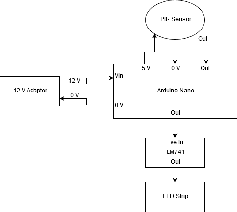
The circuit is really easy. Below is the block diagram which you can easily modify depending on the components you have.
Just go through the below circuit diagram and set up the circuit as shown. it would be better if you use a breadboard so that it would be really easy for you to troubleshoot if something comes up.
Just go through the below connections
Vin —– +ve terminal of 12 V Adapter
Gnd — -ve terminal of 12 V Adapter, -ve terminal of PIR Sensor
5 V Out — +ve terminal of PIR Sensor
Digital Pin 2—– Signal Out from PIR Sensor
Digital Pin 4—– Signal In to LM741
The Code[AdSense-C]
Simply upload the code into the Arduino
int pir=0;
void setup()
{
Serial.begin(9600);
pinMode(13, OUTPUT);
pinMode(2, INPUT);
pinMode(4, OUTPUT);
}

void loop()
{
pir = digitalRead(2);

Serial.print(" pir = ");
Serial.print(pir);

if (pir ==1))
{
digitalWrite(4, HIGH);
delay(60000);
Serial.println("Lights ON ");
}
else

{
digitalWrite(4, LOW);
Serial.println("Lights OFF ");
}

}
Output
Thats it. When there is nobody around, the output of the PIR Sensor will be 0. This values is read by Arduino and output to LM741 will be 0. LM741, operating as a comparator get no input in the +ve terminal. So the output remains 0V and the LED strip remains OFF.
When someone walks in, the PIR sensor senses the IR and the output of the PIR Sensor will be switched to 1. This values is read by Arduino and output to LM741 will be 1 for a predefined time period which can be changed in the code. LM741, operating as a comparator get an input voltage of 5V in the +ve terminal. So the output will be switched to 12V and the LED strip turns ON.[AdSense-B]
Transform a tiny DigiSpark ATtiny85 into a programmable HID keyboard with DigiKeyboard. Learn setup steps, key codes, macros, tips and inspiring project ideas.
Overview AI and Arduino are combined to create a quiz-to-unlock smart lock. OpenAI generates a short question and validates the reply; the Arduino Nano ESP32 controls a 12 V solenoid via MOSFET/relay and updates an Arduino IoT Cloud dashboard. Correct answer → brief unlock. Wrong answer → buzzer pattern and reset. Hardware remains minimal; intelligence…